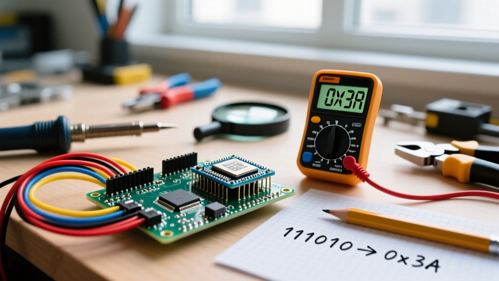

Hexadecimal is a base-16 numbering system that uses sixteen distinct symbols (0-9 and A-F) to represent values, serving as a human-readable shorthand for the binary data that microcontrollers and digital circuits actually process. If you have ever stared at an ESP32 datasheet, an I2C scanner output, or a MAC address and seen a string like 0x76 or A4:CF:12, you are looking at hexadecimal (often just called "hex"). While the physical silicon in your microcontroller only understands high and low voltage thresholds (binary 1s and 0s), hex provides a compact, readable layer for engineers to configure, address, and debug those digital systems.
The Core Concept: Why Base-16 Exists
To understand why we use base-16, you have to look at how digital memory is structured. Microcontrollers process data in bytes (8 bits). Writing out a single byte in binary requires eight digits, like 10100101. Writing it in decimal requires three digits (165). But neither of those formats maps cleanly to the underlying hardware architecture.
Hexadecimal solves this because 16 is a power of 2 (specifically, 2^4). This means exactly four binary bits (a "nibble") map perfectly to one single hexadecimal digit. Therefore, one full 8-bit byte always maps to exactly two hex digits. Think of hexadecimal like a shorthand dashboard for a mechanic: the engine only understands fuel and spark (binary), but the mechanic reads the diagnostic codes in hex because it groups the raw data into manageable, readable chunks without losing the direct hardware correlation.
Here is how the most common hex values translate across numbering systems in embedded electronics:
| Hex Value | Binary (8-bit) | Decimal | Practical Application in Electronics |
|---|---|---|---|
0x00 |
00000000 |
0 | GPIO LOW state / I2C General Call address |
0x3C |
00111100 |
60 | Standard I2C address for SSD1306 OLED displays |
0x55 |
01010101 |
85 | UART sync byte / Alternating bit pattern for signal testing |
0xAA |
10101010 |
170 | SPI Flash Read Command / Inverted alternating bit test |
0xFF |
11111111 |
255 | GPIO HIGH (with pull-up) / Maximum 8-bit PWM duty cycle |
Worked Numeric Example: Decoding an I2C Sensor
Let us look at a real-world scenario: initializing a Bosch BME280 temperature and humidity sensor over an I2C bus using an Arduino or ESP32. When you run an I2C scanner script, the serial monitor reports the sensor found at address 0x76. To verify the chip is actually a BME280 and not a different sensor sharing the bus, your code must read the Chip ID register, which the NXP I2C specification and Bosch datasheet dictate is located at register 0xD0. If the sensor is genuine, it will return the value 0x60.
Here is the numeric breakdown of what the microcontroller is actually doing on the wire:
- The Address (
0x76): In binary, this is0111 0110. In decimal, it is118. The microcontroller shifts this left by one bit to make room for the Read/Write bit, sending11101100(0xEC) on the SDA line to initiate a write sequence to that specific chip. - The Register (
0xD0): In binary, this is1101 0000. In decimal, it is208. This tells the BME280 internal multiplexer to route the data from the Chip ID memory cell onto the I2C output buffer. - The Expected Return (
0x60): In binary, this is0110 0000. In decimal, it is96. When your C++ code evaluatesif (chipID == 0x60), it is comparing the binary byte received on the wire against the binary representation of hex 60.
Wire.beginTransmission(76); instead of Wire.beginTransmission(0x76);, the compiler assumes decimal 76. Decimal 76 is 0x4C in hex. Your microcontroller will poll the wrong address, the BME280 will ignore the request, and your serial monitor will throw a "Sensor not found" error. Always use the 0x prefix in C/C++ to explicitly declare a hexadecimal literal.
Where You Meet Hexadecimal in Practice
Once you move past basic blink sketches, hex becomes the primary language of hardware configuration. Here are the three most common areas where you will need to read and write hex values on the bench.
1. Memory-Mapped Registers (ESP32 / STM32)
Modern microcontrollers do not just flip GPIO pins with simple commands; they write to specific memory addresses. According to the Espressif ESP32 Technical Reference Manual, the register that controls the output state of GPIO pins 0-31 is GPIO_OUT_REG, located at the hexadecimal memory address 0x3FF44004. If you are writing bare-metal code or debugging a bricked peripheral, you will be reading and writing 32-bit hex masks directly to these addresses.
2. Addressable RGB LEDs (WS2812B / NeoPixels)
When programming WS2812B LEDs, color is defined by a 24-bit hex value structured as 0xRRGGBB. A pure red command is 0xFF0000. Because each color channel is 8 bits (00 to FF in hex, or 0 to 255 in decimal), hex makes it trivial to mix colors. If you want a dim, warm orange, you might use 0xFF2200 (Max red, low green, zero blue). Trying to calculate and visualize that in pure binary (11111111 00100010 00000000) is virtually impossible for the human brain.
3. MAC Addresses and Network Interfaces
Every ESP32 or Raspberry Pi network interface has a unique 48-bit hardware MAC address, universally written in hex pairs separated by colons (e.g., A4:CF:12:6B:88:01). When setting up MQTT filters, MAC-based router whitelists, or ESP-NOW peer-to-peer networks, you must input these hex strings exactly as they appear on the silicon.
Common Confusions and Debugging Mistakes
Because hex sits between human-readable decimal and machine-readable binary, it is a frequent source of bench errors. Here is what you need to watch out for.
Confusing Hex with Octal (Base-8)
Octal uses digits 0-7 and is rarely used in modern embedded hardware, but it still lurks in legacy systems and Unix file permissions (like chmod 755). In C/C++, a leading zero without an 'x' denotes octal. Writing int val = 010; does not assign the decimal value ten; it assigns the octal value 10, which is decimal 8. Always use 0x for hex, and avoid leading zeros on decimal integers.
The "Physical Circuit" Fallacy
A common question from beginners is what hexadecimal actually changes in a real physical circuit or installation. The answer is: absolutely nothing. Silicon does not understand base-16. Electrons do not flow differently when you type 0xFF versus 255. Hexadecimal is purely a user-interface abstraction layer for the engineer. It changes how you configure the digital logic, but the physical circuit only ever sees the resulting high and low voltage thresholds (binary) translated by the compiler.
Endianness in Multi-Byte Hex Values
When you read a 16-bit hex value from an I2C sensor (like a raw temperature reading of 0x1A2B), you must know the sensor's "endianness". Does it send the most significant byte (0x1A) first (Big-Endian), or the least significant byte (0x2B) first (Little-Endian)? If you guess wrong, your code will read 0x2B1A, completely corrupting your sensor data. Always check the component datasheet for byte-order specifications.
Frequently Asked Questions
What is a hexadecimal in one sentence?
It is a base-16 numbering system using 0-9 and A-F that acts as a compact, human-readable translation layer for the binary data processed by digital circuits.
What do people commonly confuse hexadecimal with?
Makers most commonly confuse hex with octal (base-8), confuse hex literals with decimal values by forgetting the 0x prefix in code, or mistakenly believe hex represents a specific physical voltage level rather than a data representation format.
Do I need to memorize hex conversions?
No. You only need to memorize that 0x0 to 0xF maps to 0-15. For everything else, use the programmer mode on your Windows calculator, the macOS calculator, or an online converter. On the bench, your oscilloscope's protocol decoder will do the heavy lifting, displaying the raw I2C/SPI bytes in hex directly on the screen.


