
The Foundation: Meter Anatomy and Safety Categories
Learning how to check voltage with a multimeter is the most fundamental skill in electrical diagnostics and electronics design. However, treating a digital multimeter (DMM) as a simple plug-and-play tool is a common beginner mistake that can lead to destroyed microcontrollers, tripped breakers, or severe arc flash injuries. To build true diagnostic intuition, you must progress through a structured skill-building path—starting with safe, low-voltage DC environments before advancing to high-energy AC mains and sensitive logic circuits.
Before touching a probe to any circuit, you must understand your tool's safety architecture. According to Fluke's official multimeter safety guidelines, the Category (CAT) rating defines the meter's ability to withstand transient voltage spikes. A CAT II meter is suitable for household appliances, while CAT III is required for distribution wiring, breakers, and wall outlets. CAT IV covers the service entrance and outdoor meter bases. Never use a cheap, unrated multimeter from a discount bin to measure AC mains voltage; these often lack High Rupturing Capacity (HRC) ceramic fuses, relying instead on glass fuses that can violently explode during a short circuit fault.
Decoding CAT Ratings and Impedance
Professional meters like the Fluke 117 or the Brymen BM235 feature a standard input impedance of 10 Megohms (10MΩ). This high impedance ensures the meter draws virtually zero current from the circuit under test, preventing the 'loading effect' where the meter itself alters the voltage it is trying to measure. However, as you will learn in Level 3, this high impedance is a double-edged sword when diagnosing modern wiring.
Level 1: Testing DC Voltage (Batteries and Microcontrollers)
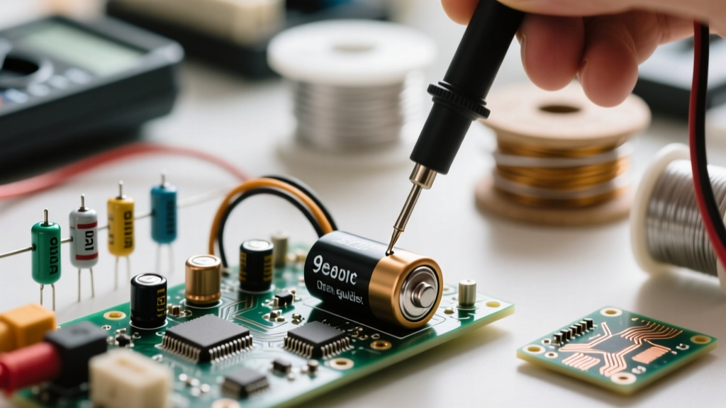
Direct Current (DC) voltage flows in a single direction, making it the safest and most predictable starting point for skill-building. Whether you are verifying a 9V alkaline battery, checking the 5V rail on an Arduino, or debugging a 12V LED strip, the physical protocol remains identical. As detailed in SparkFun's comprehensive multimeter tutorial, establishing a reliable ground reference is the key to accurate DC measurement.
The Step-by-Step DC Protocol
- Probe Placement: Insert the black probe into the COM (Common) jack and the red probe into the VΩ (Volts/Ohms) jack. Never leave the red probe in the Amps jack when measuring voltage, as this creates a dead short across your circuit.
- Dial Selection: Turn the dial to the DC Voltage setting, denoted by a 'V' with a solid line and dashed lines beneath it. If your meter is manual-ranging, select a range higher than your expected voltage (e.g., select 20V to test a 12V battery).
- Ground Reference: Touch the black probe to the circuit's ground (GND) or the negative terminal of a battery. This establishes your 0V baseline.
- Hot Probing: Touch the red probe to the positive terminal or the test point. The display will show the potential difference.
- Polarity Check: If you see a negative sign (e.g., -4.85V), your probes are reversed relative to the circuit's polarity. This won't damage a modern DMM, but it indicates you are measuring from positive to negative rather than negative to positive.
Pro Tip: When debugging microcontrollers, avoid using auto-ranging mode if you are looking for transient voltage drops. Auto-ranging meters take a fraction of a second to 'hunt' for the correct decimal placement, which can cause you to miss a brief brownout condition on a 3.3V logic pin. Switch to manual ranging (e.g., the 4V or 6V scale) for faster sample rates.
Level 2: Measuring AC Voltage (Mains and Appliances)
Alternating Current (AC) introduces frequency, phase, and peak-to-peak variations. In North America, a standard wall outlet nominally provides 120V AC at 60Hz, but the actual peak voltage reaches roughly 170V. Measuring AC mains requires strict adherence to safety protocols, as the energy available in a residential panel is more than enough to cause fatal ventricular fibrillation.
True-RMS vs. Average-Responding Meters
When you upgrade from testing basic resistive loads (like incandescent bulbs or space heaters) to modern electronics (like LED drivers, variable frequency drives, or switching power supplies), the waveform becomes distorted. An 'average-responding' multimeter assumes a perfect sine wave and will output highly inaccurate readings on non-linear loads. To accurately check voltage with a multimeter in modern environments, you must use a True-RMS (Root Mean Square) meter. True-RMS meters calculate the equivalent heating effect of the distorted waveform, providing the actual effective voltage regardless of harmonic distortion.
The One-Hand Rule for AC Mains
The Occupational Safety and Health Administration (OSHA) mandates strict protocols for working near energized parts. When probing a live 120V or 240V receptacle, adopt the 'one-hand rule.' Keep your non-dominant hand in your pocket or firmly behind your back. If a fault occurs and current enters your body, this practice prevents the electricity from crossing your chest cavity and disrupting your heart rhythm. Use your dominant hand to manipulate both probes, or use alligator clip leads to secure the ground connection before applying the hot probe.
Level 3: Advanced Diagnostics (Ghost Voltage and Logic Levels)
Once you master basic DC and AC measurements, you will inevitably encounter readings that defy basic logic. The most common point of confusion for intermediate technicians is 'ghost voltage' or 'phantom voltage.' This occurs when you measure an open circuit or a disconnected wire that runs parallel to a live, energized wire in the same conduit.
Defeating Ghost Voltage with LoZ
Because standard DMMs have a 10MΩ input impedance, they act like highly sensitive antennas. The capacitive coupling between the live wire and the dead wire induces a tiny, harmless alternating current. The high-impedance meter reads this induced field as a legitimate voltage, often displaying anywhere from 20V to 90V on a wire that is actually completely dead. This leads to misdiagnosed open neutrals or false assumptions about switched loops.
To solve this, advanced meters feature a LoZ (Low Impedance) mode. Engaging LoZ drops the meter's internal impedance from 10MΩ down to roughly 3kΩ. This creates a minor load on the circuit, instantly bleeding off the harmless capacitive ghost voltage and dropping the display to 0.0V, confirming the wire is truly de-energized. Warning: Never use LoZ mode on sensitive, low-energy electronic circuits or microcontroller I/O pins, as the 3kΩ load will draw enough current to pull down the logic level and potentially damage the driving IC.
Troubleshooting Matrix: Common Voltage Reading Anomalies
Use this diagnostic matrix to quickly identify why your multimeter might be displaying unexpected voltage readings during your skill-building exercises.
| Symptom / Reading | Probable Cause | Diagnostic Solution |
|---|---|---|
| Fluctuating DC voltage on a 5V rail | Switching regulator ripple or poor ground reference. | Ensure black probe is on a dedicated ground plane, not a high-current return path. Use an oscilloscope for ripple analysis. |
| Reading ~40V-80V on a disconnected AC wire | Capacitive coupling (Ghost Voltage) from adjacent live wires. | Switch the multimeter to LoZ (Low Impedance) mode to bleed off the induced phantom voltage. |
| AC voltage reads significantly lower than expected (e.g., 95V instead of 120V) | Using an average-responding meter on a non-linear, distorted waveform. | Upgrade to a True-RMS multimeter to accurately measure the heating equivalent of the distorted wave. |
| Meter reads 'OL' or '1' on a known live battery | Blown internal DMM fuse or selected wrong measurement function (e.g., Ohms instead of Volts). | Verify dial position. Check internal HRC fuses with a continuity test. Replace with exact OEM rated fuses. |
| 3.3V logic pin reads 1.8V | Floating ground reference or voltage divider effect from high-impedance pull-up resistors. | Verify ground probe contact. Check if the pin is being actively driven or if it is in a high-impedance (Hi-Z) state. |
The Golden Rule of Diagnostics: A multimeter only tells you the potential difference between two specific points in space and time. If a voltage reading makes no sense, your ground reference is almost certainly compromised. Always verify your meter's functionality on a known live source before and after testing a dead circuit to ensure your leads haven't internally fractured.
Mastering how to check voltage with a multimeter is not just about reading a digital display; it is about understanding the electrical environment you are probing. By progressing from safe DC battery tests to understanding the nuances of True-RMS AC measurement and LoZ ghost voltage elimination, you transition from a simple parts-changer to a true diagnostic technician. Invest in a properly rated CAT III/IV True-RMS meter, respect the energy of the circuits you work on, and let the data guide your troubleshooting logic.


