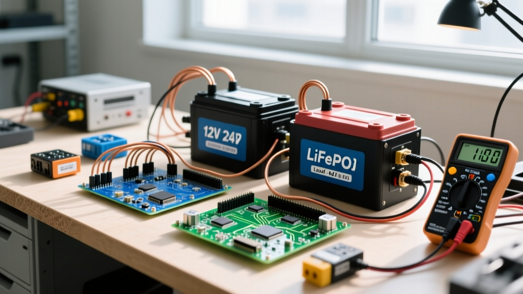
When adding batteries to a solar system, you cannot simply bolt new cells onto an existing bank and expect them to balance. You must match the new bank's nominal voltage to the inverter, recalculate the charge controller's amperage output to stay within the battery's specific C-rate limits, and never parallel mismatched chemistries or ages. The direct answer to 'how do I add capacity?' is to build a completely new, matched battery bank wired to the correct series/parallel topology for your inverter's DC bus, and upgrade your MPPT charge controller to supply the required charge current.
To understand why, we have to look at the complete system block. In a standard DC-coupled solar-plus-storage architecture, power flows from the Source (PV array) to the MPPT Charge Controller, which regulates voltage and current to the Battery Bank (the DC bus). From there, the Inverter/Charger draws DC power, converts it to AC, and feeds the Load (your main panel or critical loads subpanel). Every component in this chain must be sized for the weakest link's charge and discharge limits.
System Architecture and the Chemistry Decision
Before buying more cells, you must define the usable capacity of your chosen chemistry. Nameplate capacity (Ah) is a marketing number; usable capacity is dictated by Depth of Discharge (DoD) limits, round-trip efficiency, and Peukert's Law. If you are adding batteries to a solar system to run a 3,000W continuous load for 4 hours, your raw energy requirement is 12,000Wh (12 kWh). But you must account for system losses.
Assuming a high-frequency hybrid inverter at 92% efficiency and a battery round-trip efficiency of 95% (typical for LiFePO4), the actual energy the battery must deliver is 12,000Wh / (0.92 × 0.95) = 13,771Wh. If you are using LiFePO4 with an 80% DoD limit to preserve cycle life, your required nameplate capacity is 13,771 / 0.80 = 17,213Wh. On a 48V nominal system, that equates to a 358Ah battery bank.
If you attempt this same calculation with Flooded Lead-Acid (FLA), the math changes drastically due to Peukert's Law. Peukert's exponent (k ≈ 1.3 for FLA) dictates that as discharge current increases, effective capacity drops. A 400Ah FLA bank rated at a 20-hour discharge rate (C/20) will only deliver roughly 250Ah if you pull it down over 4 hours. Furthermore, FLA is limited to a 50% DoD. The table below breaks down the real-world sizing parameters you must use when selecting your chemistry.
| Chemistry | Usable DoD Limit | Max Charge C-Rate | Round-Trip Efficiency | Cycle Life (to 80% SoH) | Approx. Cost/kWh (2026) |
|---|---|---|---|---|---|
| Flooded Lead-Acid (FLA) | 50% | 0.1C to 0.15C | 75% - 80% | 500 - 800 | $150 - $200 |
| AGM (Absorbent Glass Mat) | 50% | 0.2C | 80% - 85% | 600 - 1,000 | $250 - $320 |
| LiFePO4 (Lithium Iron Phosphate) | 80% - 90% | 0.5C (up to 1.0C) | 95% - 98% | 4,000 - 6,000+ | $180 - $280 |
| NMC (Lithium Nickel Manganese Cobalt) | 80% - 90% | 0.5C to 1.0C | 92% - 96% | 1,500 - 2,500 | $220 - $300 |
Series vs. Parallel Topologies and Charge Limits
Once you have your target Ah, you must wire the physical blocks to match your inverter's DC bus voltage (usually 12V, 24V, or 48V). The rules of series and parallel wiring dictate how voltage and capacity scale, which directly impacts your wire sizing and BMS (Battery Management System) requirements.
| Topology | What Adds Up? | What Stays the Same? | Primary Consequence & Use Case |
|---|---|---|---|
| Series | Voltage (V) | Capacity (Ah) | Reduces DC current for the same wattage, allowing smaller wire gauges. Used to step 12V blocks up to a 48V inverter bus. |
| Parallel | Capacity (Ah) | Voltage (V) | Increases total energy storage but multiplies DC current. Requires massive busbars and careful current balancing to prevent one string from overworking. |
| Series-Parallel | Both V and Ah | Nothing | The standard for large 48V banks (e.g., four 12V 100Ah batteries in series, then paralleled with another identical string of four). Requires diagonal wiring for balance. |
When wiring in parallel, the charge and discharge limits of your specific chemistry become critical. If you parallel two strings of LiFePO4, the BMS in each battery must handle the combined current if a fault occurs. More importantly, you must respect the manufacturer's maximum charge C-rate. A 0.5C charge rate on a 400Ah LiFePO4 bank means you can safely push 200A of charge current into the bank. If your solar array and MPPT controller can only produce 60A, you are charging at 0.15C. While safe, it will take nearly 7 hours of peak sun to recharge a depleted bank, which may not be feasible in winter months.
For lead-acid batteries, the charge limit is much stricter. Pushing a 0.5C charge rate into an AGM battery will cause excessive gassing, thermal runaway, and rapid degradation of the absorbed glass mat. Always cap lead-acid charge currents at 0.1C to 0.2C (e.g., 40A to 80A for a 400Ah bank).
Sizing the Inverter and Charge Controller for the New Bank
Adding batteries to a solar system almost always exposes a bottleneck in the charge controller or the inverter's internal charger. If you are expanding a 200Ah 48V LiFePO4 bank to 400Ah, your MPPT charge controller must be upgraded to deliver the necessary amperage.
To size the MPPT controller, use the formula: Required Solar Wattage = (Battery Ah × Target C-Rate) × System Voltage. For a 400Ah LiFePO4 bank targeting a conservative 0.3C charge rate, you need 120A of charge current. At a nominal 48V (actual charging voltage around 54V), that requires 6,480W of solar input. You would need an MPPT controller rated for at least 120A, such as the Victron SmartSolar MPPT 250/120, or two smaller controllers paralleled via CAN bus.
On the AC side, the inverter's internal pass-through and surge capabilities must match the load. A 48V 400Ah bank can theoretically deliver 19.2 kWh of energy. If you pair this with a 3,000W inverter, you can only pull 62A continuously from the battery bank (3000W / 48V). This is well within standard 2/0 AWG copper wiring limits. However, if you install an 8,000W inverter, a sustained 8kW load will pull 166A from the bank. You must verify that the battery's BMS is rated for 200A continuous discharge and that your busbars and interconnect cables are sized for at least 200A (requiring 2/0 AWG or 4/0 AWG depending on insulation temperature ratings and conduit derating).
Furthermore, if you are using a hybrid inverter with an integrated AC charger (for generator or grid charging), ensure the charger's output is adjustable. A solar-plus-storage system relies on the inverter's ability to throttle charge current so it doesn't trip the AC breaker on the generator or grid tie-in point.
Integration Rules and Fire Safety Protocols
The most common catastrophic mistake when adding batteries to a solar system is attempting to parallel a new battery with an old one, or mixing different chemistries. If you parallel a brand-new 100Ah LiFePO4 battery with a 3-year-old 100Ah LiFePO4 battery, their internal resistances and state-of-health (SoH) curves will differ. The newer battery will accept charge faster, hit its high-voltage cutoff first, and force its BMS to disconnect. The older battery will then take the full brunt of the solar charge current, potentially exceeding its C-rate limit and triggering a thermal event.
Never parallel mismatched lithium cells, different capacities, or batteries from different manufacturers. According to Battery University safety guidelines, a compromised cell or a BMS failure in a parallel string can cause the healthy batteries to dump their entire short-circuit current into the failed cell, leading to thermal runaway. Always build a new, matched bank. If you must expand an existing LiFePO4 bank, the new batteries must be the exact same model, and all batteries must be manually top-balanced to exactly 3.65V per cell before being connected in parallel. Install a Class D fire extinguisher or an automatic aerosol fire suppression module inside the battery enclosure.
Finally, verify your physical connections. When adding batteries, torque every terminal lug to the manufacturer's specification (usually 5 to 7 Nm for M8 terminals). Use a calibrated torque wrench, not a hand-tightened guess. Loose connections on a 48V DC bus carrying 150A will generate immense heat, melting insulation and causing DC arc faults. After torquing, apply a layer of dielectric grease or clear nail polish over the nut-and-bolt interface as a visual torque-seal and corrosion barrier. Run the system under a heavy load for 30 minutes, then use a thermal camera or infrared thermometer to scan every busbar and lug; any connection reading more than 10°C above ambient requires re-crimping or re-torquing.