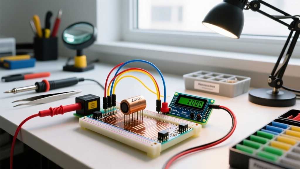
Wide bandgap (WBG) electrical engineering technologies refer to semiconductor materials—primarily Silicon Carbide (SiC) and Gallium Nitride (GaN)—that possess a larger electronic bandgap than traditional silicon, enabling operation at vastly higher voltages, temperatures, and switching frequencies. When you swap a legacy silicon MOSFET or IGBT for a WBG device in a power circuit, it fundamentally changes the physical footprint and thermal management requirements of the design; by switching at 100kHz+ instead of 20kHz, you can shrink inductors and capacitors by 50% to 80%, and by running at 150°C+ junction temperatures, you drastically reduce heatsink mass. However, a common and destructive confusion among hobbyists and junior engineers is treating WBG components as drop-in silicon replacements. A GaN HEMT is not a standard MOSFET; its gate threshold and maximum gate-source voltage limits are entirely different, and driving it with a standard 15V silicon gate driver will instantly destroy the silicon.
The Core Physics: Bandgap and Breakdown Fields
To understand why these materials behave differently, we have to look at the atomic physics of the semiconductor crystal. The 'bandgap' is the energy (measured in electron-volts, eV) required to excite an electron from the valence band into the conduction band. Think of the bandgap as the height of a retaining wall holding back water (electrons); a wider bandgap means a much taller wall, requiring vastly more energy (heat or voltage) to spill over.
Traditional silicon has a bandgap of 1.1 eV. Silicon Carbide (SiC) sits at roughly 3.2 eV, and Gallium Nitride (GaN) is around 3.4 eV. This 3x increase in bandgap energy translates to a critical electric field (breakdown voltage) that is nearly 10 times higher than silicon.
Because the material can withstand a much higher electric field before breaking down, engineers can make the drift region of the transistor 10 times thinner and dope it 100 times more heavily. This physical shrinking of the internal structure directly reduces the on-state resistance ($R_{DS(on)}$) and the parasitic capacitances ($C_{oss}$, $C_{rss}$) that cause switching delays. According to the U.S. Department of Energy's AMMTO program, this atomic-level advantage is what allows WBG devices to reduce energy losses in power conversion by up to 50% compared to legacy silicon.
Worked Example: Switching Losses in a 2kW DC-DC Converter
Let us put real numbers to this theory by comparing a traditional 600V Silicon IGBT against a modern 650V GaN FET in a hard-switched 2kW DC-DC bridge topology. The formula for switching power loss is:
P_sw = (E_on + E_off) × f_sw
Scenario A: 600V Silicon IGBT (e.g., Legacy 40A Part)
- Switching Energy ($E_{on} + E_{off}$): ~2.5 mJ per cycle (limited by the 'tail current' inherent to IGBT minority carrier recombination).
- Max Practical Frequency ($f_{sw}$): 20 kHz (pushing higher causes thermal runaway due to switching losses).
- Calculation: 2.5 mJ × 20,000 Hz = 50 Watts of pure heat dissipated per switch just from turning on and off.
Scenario B: 650V GaN FET (e.g., Navitas NV6125 or similar)
- Switching Energy ($E_{on} + E_{off}$): ~0.05 mJ per cycle (GaN is a majority carrier device; there is zero tail current and virtually zero reverse recovery charge).
- Practical Frequency ($f_{sw}$): 100 kHz (easily achievable due to low $Q_g$ gate charge).
- Calculation: 0.05 mJ × 100,000 Hz = 5 Watts of switching loss per switch.
The Result: The GaN implementation operates at five times the switching frequency, which allows you to use an inductor with 1/5th the inductance (and physical volume), while generating one-tenth the switching heat. This is why modern 100W USB-C chargers fit inside a hockey puck rather than a brick.
Where You Meet This in Practice
You are likely already interacting with WBG electrical engineering technologies daily, even if you do not see the bare silicon. Here is where these components dominate modern electrical design:
- Consumer Fast Charging (GaN): High-density USB-C Power Delivery (PD) adapters (65W to 140W) use GaN to achieve power densities exceeding 20W/in³. The high frequency pushes the magnetic components into the sub-millimeter range.
- Electric Vehicle Traction Inverters (SiC): The main drive inverters in 800V EV architectures (like the Porsche Taycan or Hyundai Ioniq 5) use SiC MOSFET modules. SiC's superior thermal conductivity allows the inverter to handle 400A+ pulses while bolted directly to a liquid cooling plate.
- Solar String Inverters (SiC): Residential and commercial solar inverters use SiC to boost DC panel voltages up to 800V+ before inversion, minimizing $I^2R$ line losses across the array wiring.
- Data Center Power Supplies (GaN/SiC): Titanium-rated server power supplies use WBG totems to achieve 98%+ efficiency at 50% load, reducing HVAC cooling costs in server farms.
Design Trade-Offs and Gate Drive Realities
While the fundamentals of Silicon Carbide and GaN are well-documented, the practical reality of designing with them requires unlearning decades of silicon habits. Below is a comparison of the critical parameters you must respect when selecting a driver and laying out the PCB.
| Parameter | Silicon MOSFET | Silicon Carbide (SiC) | Gallium Nitride (GaN) |
|---|---|---|---|
| Max Gate-Source Voltage ($V_{GS}$) | ±20V | +25V / -10V (Typical drive: +18V / -4V) | +7V / -10V (Typical drive: +6V) |
| Miller Plateau Voltage | ~4V to 6V | ~3V to 5V | ~1.5V to 2.5V |
| Negative Gate Bias Required? | Rarely (usually 0V off) | Yes (-3V to -5V to prevent Miller turn-on) | Sometimes (depends on $dv/dt$ immunity) |
| Common Source Inductance Tolerance | Forgiving (nH range) | Strict (requires Kelvin source connections) | Extreme (requires integrated gate loops) |
If you take a standard 15V isolated gate driver meant for a silicon IGBT and connect it to an enhancement-mode GaN transistor, you will exceed the GaN device's absolute maximum $V_{GS}$ rating (usually 6V or 7V) by more than double. The gate oxide will rupture instantly, shorting the gate to the source and destroying the component. Always use dedicated GaN drivers with integrated level shifters or strict voltage clamping.
Frequently Asked Questions
Why do GaN electrical engineering technologies require specialized gate drivers?
GaN transistors have an incredibly low gate charge ($Q_g$) and a very low threshold voltage ($V_{th}$), often around 1.2V to 1.5V. Standard silicon drivers output 12V to 15V, which will instantly punch through the thin gate dielectric of a GaN device, which typically maxes out at 6V or 7V. Furthermore, because GaN switches so fast (often exceeding 100V/ns), the parasitic inductance in a standard driver trace will cause massive gate ringing. Specialized GaN drivers are integrated directly into the same package or placed millimeters away, featuring tightly regulated 5V/6V outputs and high sink/source current capabilities (often 4A to 6A peak) to charge the gate in nanoseconds without overshoot.
Can I use Silicon Carbide (SiC) for low-voltage 12V DC applications?
Technically yes, but economically and electrically, it is a poor choice. SiC is engineered to solve high-voltage (600V to 3300V) drift region resistance problems. At 12V or 48V, the drift region in a silicon MOSFET is already so thin that its $R_{DS(on)}$ is exceptionally low (often under 1 milliohm). Using a 650V SiC MOSFET in a 12V circuit means you are paying a massive premium for voltage blocking capability you do not need, while actually suffering from higher gate charge requirements and worse $R_{DS(on)}$ compared to a cheap 30V silicon trench MOSFET. Stick to silicon for sub-100V applications.
How do WBG technologies affect electromagnetic interference (EMI) in a layout?
WBG devices are notorious for creating severe EMI headaches if the PCB layout is not optimized. Because SiC and GaN can achieve $dv/dt$ (voltage slew rates) of 50V/ns to over 100V/ns, any stray parasitic capacitance between the switching node and the chassis ground will inject massive high-frequency common-mode currents ($I = C imes dv/dt$). This high-frequency noise easily bypasses standard EMI filters designed for 20kHz silicon switching edges. To mitigate this, designers must minimize the physical area of the high-frequency switching loop, use symmetrical PCB routing, implement multi-stage EMI filters with high-frequency nanocrystalline cores, and often intentionally slow down the gate turn-on speed slightly via a gate resistor to trade a fraction of efficiency for EMI compliance.