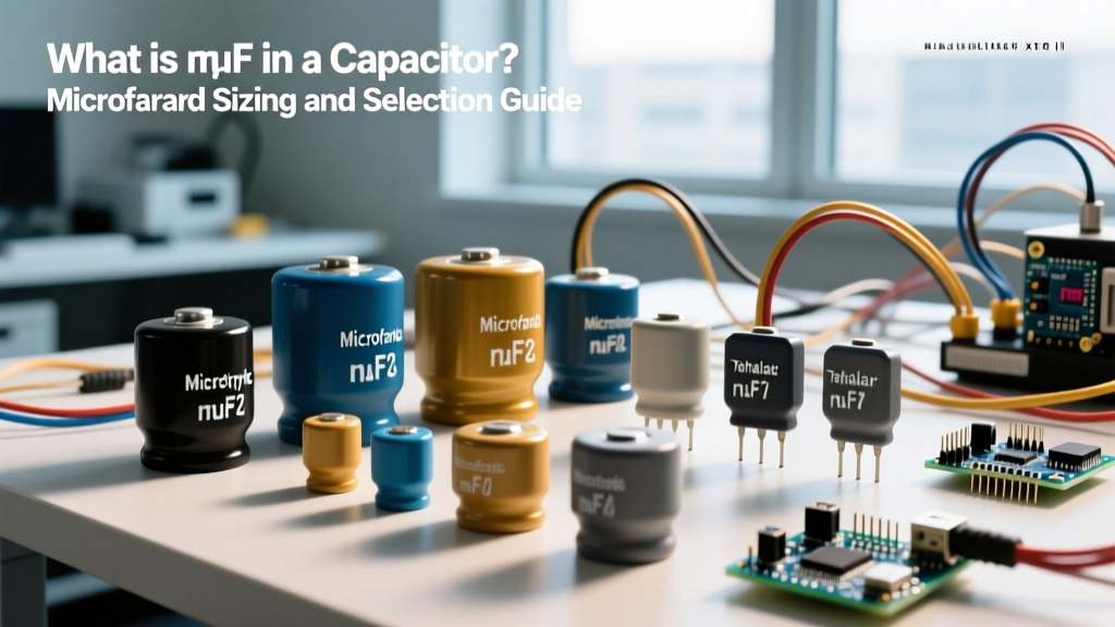

The symbol µF stands for microfarad, which is one-millionth of a Farad (10-6 F). It is the standard unit used to measure a capacitor's ability to store electrical charge. If a capacitor is rated at 1 µF, it stores 1 microcoulomb of charge per volt applied across its terminals. In practical bench terms, the µF rating dictates how much energy the component can buffer, how low of a frequency it can filter, and how fast it can supply transient current to an IC.
To put a real number on it: a 1000µF aluminum electrolytic capacitor charged to 12V stores exactly 0.072 Joules of energy (calculated via E = ½CV²). That is enough to keep a 50mA microcontroller alive for roughly 150 milliseconds during a brownout—just enough time to write critical data to EEPROM.
Reading the Silkscreen: How to Decode Capacitor Markings
Knowing what µF means is only half the battle; you have to be able to read it off the physical part. Manufacturers use two primary marking schemes depending on the physical size and dielectric of the capacitor.
Direct Printing (Electrolytic and Large Film)
Through-hole aluminum electrolytics and large film capacitors have enough surface area to print the value directly. You will see 470µF 25V printed on the sleeve. The negative stripe on the sleeve indicates the cathode (negative lead). For axial capacitors, the stripe marks the positive anode—always verify the datasheet if the polarity marker is ambiguous.
The 3-Digit EIA Code (Ceramic MLCCs and Small Film)
Small ceramic disc and surface-mount MLCC (Multi-Layer Ceramic Capacitor) parts use a 3-digit picofarad (pF) multiplier code. This is where most hobbyists get tripped up. The first two digits are the significant figures, and the third digit is the multiplier (number of zeros to add), yielding a value in picofarads.
- 104: 10 followed by 4 zeros = 100,000 pF. Since 1,000,000 pF = 1 µF, 100,000 pF = 0.1 µF (or 100nF). This is the universal bypass cap.
- 473: 47 followed by 3 zeros = 47,000 pF = 0.047 µF.
- 225: 22 followed by 5 zeros = 2,200,000 pF = 2.2 µF.
You will often see a letter suffix indicating tolerance: J = ±5%, K = ±10%, M = ±20%. A marking of 104K is a 0.1µF capacitor with a 10% tolerance.
Dielectric Showdown: Which Capacitor Type for Which Job?
You cannot just grab any 10µF capacitor and drop it into any circuit. The dielectric material inside dictates the Equivalent Series Resistance (ESR), temperature stability, and microphonic noise. Here is the definitive selection matrix.
| Dielectric Type | Construction | Typical Tolerance | Tempco (Temp Stability) | Best Application |
|---|---|---|---|---|
| MLCC (X7R/X5R) | Ceramic layers | ±10% to ±20% | Moderate (±15% over temp) | IC decoupling, general bypass, SMPS filtering |
| MLCC (C0G/NP0) | Para-electric ceramic | ±1% to ±5% | Zero (±30ppm/°C) | RF oscillators, precision filters, audio signal path |
| Aluminum Electrolytic | Etched foil + liquid electrolyte | -20% / +80% | High (varies widely) | Bulk power supply smoothing, low-frequency coupling |
| Film (Polypropylene) | Metalized plastic film | ±1% to ±5% | Very Low | Audio crossovers, high-voltage snubbers, motor run |
| Tantalum (Polymer) | Porous Ta anode + polymer cathode | ±10% to ±20% | Moderate | Space-constrained bulk decoupling, portable medical |
The Substitution Matrix: Swapping Parts Safely
When your parts bin is missing the exact BOM component, you need to know what you can safely swap without causing oscillation, ripple, or a fire. According to fundamental circuit theory, capacitance and voltage ratings interact differently depending on the circuit block.
Voltage Rating Substitution
Rule: ALWAYS substitute with a higher or equal voltage rating. Never go lower. If the schematic calls for a 16V cap in a 12V rail, a 25V or 50V cap is perfectly safe. The only penalty is a slightly larger physical footprint and, in high-frequency RF circuits, a marginally higher parasitic inductance due to the larger case size.
Capacitance (µF) Substitution
- Power Supply Bulk Filtering: You can safely increase the µF value by up to 2x or 3x. Swapping a 470µF for a 1000µF will reduce ripple voltage. Warning: Going too high (e.g., 10,000µF) may trip the inrush current protection of your upstream fuse or damage the rectifier diodes at power-on.
- IC Decoupling (Bypass): Stick to the exact value (usually 0.1µF). Increasing it to 1µF can cause resonance issues with the PCB trace inductance, creating an impedance peak that fails to suppress high-frequency switching noise.
- Timing and Oscillators (555 timers, RC filters): MUST match exactly. The frequency is dictated by f = 1 / (2πRC). A 20% tolerance swap will shift your cutoff frequency or PWM duty cycle out of spec.
Failure Modes: Visual Symptoms of a Blown Cap
Capacitors are the most common point of failure in aging electronics. Identifying a failed cap by its visual symptoms saves hours of multimeter probing. Application guides from major manufacturers detail these specific degradation mechanisms.
Aluminum Electrolytic: The Domed Top
Visual Symptom: The top of the can is bulging upward, or the cross-vent on top has split open. You may see a brown, crusty residue leaked from the bottom rubber bung. The Physics: The liquid electrolyte boils and generates hydrogen gas due to excessive ripple current or reverse voltage. The internal pressure forces the vent open to prevent an explosion. Measure it with an ESR meter; it will read open or show massively elevated ESR.
MLCC Ceramic: The Invisible Fracture
Visual Symptom: Often looks perfectly fine to the naked eye. Under a 10x loupe, you might see a hairline crack near the solder pad. The Physics: Ceramic is brittle. PCB flexure during assembly or thermal shock from a hot soldering iron causes 'flex cracking'. The internal plates short together. The cap will measure 0 ohms on a multimeter, effectively dead-shorting the power rail.
Tantalum: Thermal Runaway
Visual Symptom: A black scorch mark on the PCB, a melted or cracked epoxy body, and the distinct smell of burnt plastic. The Physics: Tantalum caps fail as a dead short. If the circuit can supply high current, the short causes localized heating, which lowers the cap's internal resistance further, drawing more current until it catches fire. Always use a current-limiting resistor or a polymer tantalum variant for high-current rails.
The Decision Path: Pick Your Exact Part in 60 Seconds
Stop guessing. Use this decision tree to select the exact part number for your next build or repair. These are industry-standard, readily available KEMET and Panasonic series that you can source from any major distributor.
| If your application is... | Then choose this Dielectric & Value | Concrete Part Number (Order This) |
|---|---|---|
| Bypassing a digital IC (ESP32, Arduino, 74HC595) | 0.1µF X7R Ceramic (MLCC) | KEMET C0805C104K5RACTU (0805 SMD, 50V, 10%) |
| Smoothing a 12V-24V DC power supply output | 470µF to 1000µF Low-ESR Aluminum Electrolytic | Panasonic EEU-FR1E102 (1000µF, 25V, Radial, 105°C) |
| Building an audio crossover or DAC filter | 1µF to 10µF Polypropylene Film | WIMA MKP1O12100C000JSSD (1000pF/1nF - use MKP10 series for 1µF+) |
| RF matching network or precision 555 timer | 10pF to 1000pF C0G/NP0 Ceramic | KEMET C315C100J1G5TA (10pF, 100V, 5%, Radial) |
When in doubt on a general-purpose DIY prototyping board, stock your bench with 0.1µF X7R ceramics and 100µF 25V electrolytics. Those two values and dielectrics will solve 90% of the decoupling and bulk-filtering problems you encounter in sub-30V hobbyist circuits.


