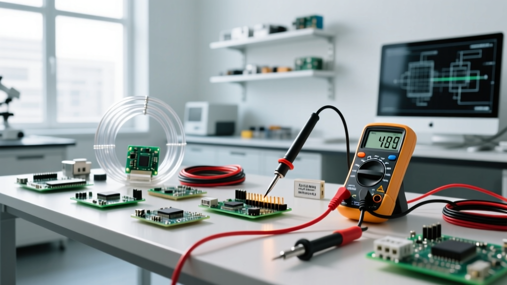

The Direct Answer: What Is Measured in Volts?
When you ask what is measured in volts, the strict physics answer is electrical potential difference between two specific points in a circuit. Voltage (measured in volts, symbol V) is the electromotive force that pushes electrons through a conductor. If current (amps) is the volume of water flowing through a pipe, voltage is the water pressure pushing it. Without a difference in pressure between point A and point B, no water flows; without a difference in potential (voltage), no current flows.
In practical bench and jobsite terms, measuring volts tells you if a power source is alive, if it is delivering the correct pressure to a load, and if there is unintended resistance in the wiring. For a standard US residential 120V AC branch circuit, the nominal target is 120V, but a good reading is anywhere from 114V to 126V (per ANSI C84.1 standards). If you measure 108V at a receptacle under load, you don't just have a 'low number'—you have a severe voltage drop condition that will overheat motors and trip breakers.
Meter Setup and Safety Categories (CAT Ratings)
Before touching a probe to a terminal, your multimeter must be configured correctly and rated for the environment. Measuring voltage at a 5V Arduino pin is vastly different from measuring a 240V dryer outlet.
Any procedure involving mains voltage (>50V AC / >120V DC) carries a risk of lethal shock or arc flash. Whenever possible, de-energize the circuit, lock/tag out the breaker, and verify dead with a tested non-contact voltage tester or meter before touching bare conductors. If live-testing is strictly necessary, use a meter rated for the environment and wear appropriate PPE. Local code (NEC-style guidance) may require a licensed electrician for panel-level work.
Meter Setup Block
- Lead Jacks: Plug the black lead into the COM (common) jack. Plug the red lead into the V/Ω (volts/ohms) jack. Never leave the red lead in the 'A' (amps) jack when measuring voltage; this creates a dead short across the source and will blow the meter's internal fuse or cause an arc flash.
- Dial Position: Turn the dial to V~ (or VAC) for alternating current (wall outlets, transformers) or V⎓ (or VDC) for direct current (batteries, solar panels, logic boards).
- Range Selection: If using a manual-ranging meter, select a range higher than your expected voltage (e.g., select the 200V range for a 120V circuit, or the 20V range for a 12V battery). Auto-ranging meters will handle this automatically, but manual ranging is faster for repetitive testing.
Understanding CAT Ratings
The Fluke guide on CAT ratings and the IEC 61010-1 standard define measurement categories based on transient overvoltage risks. A CAT II meter is fine for testing household appliances and receptacles. However, if you are measuring at the main service panel, outdoor service entrance, or utility drop, you must use a CAT III or CAT IV rated meter. A CAT II meter subjected to a utility-side transient spike can arc internally, causing severe burns.
Probe Placement and Expected Readings by Circuit
Where you place your probes dictates what you are actually measuring. Voltage is always measured in parallel with the component or source. You never break the circuit to measure volts (that is for amps).
| Test Point | Probe Placement | Expected (Good) | Bad Reading | Diagnostic Meaning |
|---|---|---|---|---|
| 120V Duplex Receptacle | Red to Hot (short slot), Black to Neutral (long slot) | 114V – 126V AC | < 110V or > 130V | High voltage drop on branch, loose neutral, or utility transformer tap issue. |
| 12V Lead-Acid Battery (Automotive) | Red to Pos (+), Black to Neg (-), engine off | 12.4V – 12.7V DC | < 12.0V DC | Sulfated cell, parasitic draw, or alternator failing to charge. |
| 240V Dryer Outlet (NEMA 14-30) | Red to Line 1, Black to Line 2 | 228V – 252V AC | 120V AC | One pole of the double-pole breaker has tripped or a feeder leg is open. |
| 5V Arduino/ESP32 Logic Pin | Red to 5V/VIN pin, Black to GND pin | 4.8V – 5.2V DC | < 4.5V DC | USB cable voltage drop, inadequate power supply, or onboard regulator overheating. |
Common Mistakes That Give Misleading Voltage Readings
If your meter shows a voltage but the circuit isn't behaving correctly, you are likely falling victim to one of these measurement traps:
Measuring Open-Circuit vs. Closed-Circuit: A failing 12V power supply might read a perfect 12.5V DC when nothing is connected (open circuit). But the moment you connect a 5A load, the voltage sags to 8V due to internal resistance. Always measure voltage while the circuit is under its normal operating load to get a true picture of system health.
The Loose Probe Connection: Pushing probe tips into the plastic face of a receptacle rather than making firm metal-to-metal contact with the internal contacts adds series resistance. This artificially lowers your reading. Use alligator clip adapters or probe tip extensions for hands-free, solid connections.
Voltage Troubleshooting Decision Tree
When a 120V load (like a window AC unit or table saw) is underperforming or tripping its internal thermal overload, follow this decision path to isolate the fault. This framework relies on NFPA 70 (NEC) guidelines for acceptable voltage drop (typically <3% on branch circuits).
| Step | Measurement Action | If Result is TRUE (Good) | If Result is FALSE (Bad) |
|---|---|---|---|
| 1 | Measure voltage at the main panel breaker terminals (Line to Neutral). | Reading is 118V - 122V. Proceed to Step 2. | Reading is < 115V. Action: Fault is upstream. Call utility to check transformer taps. |
| 2 | Measure voltage at the receptacle under full load (device turned ON). | Reading is > 114V (Drop is < 3%). Proceed to Step 3. | Reading is < 114V (Drop is > 3%). Action: Proceed to Step 4. |
| 3 | Device still underperforms despite good receptacle voltage. | N/A | Action: The fault is inside the appliance (bad motor capacitor, failing winding). Repair appliance. |
| 4 | Calculate wire run length. Is the one-way distance from panel to receptacle over 50 feet on 14 AWG wire? | Yes, distance is > 50 feet. | No, distance is short. Action: Check for loose neutral bus bar lug or corroded receptacle terminals. |
| 5 | Terminal Decision: Wire is too thin for the distance under load. | FINAL ACTION: Pull new 12 AWG THHN copper conductors through the conduit, or upgrade the branch circuit to 10 AWG NM-B (Romex) if the one-way run exceeds 75 feet. Upgrade breaker to match new wire ampacity (20A for 12 AWG, 30A for 10 AWG if permitted by device). | |
Recommended Multimeters for Voltage Testing in 2026
To execute these measurements safely and accurately, you need a reliable tool. Here are the concrete picks based on bench and jobsite requirements for 2026:
- The Professional Standard: Fluke 117 True RMS Multimeter (~$210). Features AutoVolt (automatic AC/DC selection), LoZ mode to eliminate ghost voltages, and a CAT III 600V / CAT IV 300V safety rating. This is the default choice for HVAC techs and residential electricians.
- The Best Value for Makers: Brymen BM235 (~$105). Offered by various rebrands (like the Greenlee DM-830), this meter punches way above its weight with excellent input protection, fast continuity, and a true CAT III rating. Ideal for advanced DIYers and panel builders.
- The Budget Bench Pick: Klein Tools MM400 (~$55). A solid CAT III 600V auto-ranging meter. It lacks LoZ and the rugged drop-protection of a Fluke, but it is perfectly adequate for low-voltage DC electronics, Arduino projects, and basic 120V receptacle checks where arc-flash risk is minimal.
Understanding what is measured in volts is only the first step; knowing how to interpret those numbers under load, in the correct safety category, and with the right test equipment is what separates a guesser from a troubleshooter. Always verify your meter's battery level before trusting a zero-voltage reading on a live circuit, and when in doubt, measure twice.


