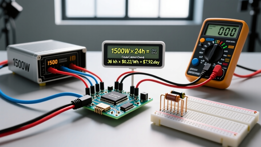
An electrical unit is a standardized, internationally agreed-upon measurement used to quantify a specific electrical property—like current, voltage, or resistance—so we can calculate, build, and troubleshoot circuits with exact precision. Without these standardized units, specifying a component or sizing a wire would be impossible, as we would have no common language to describe the physical forces moving through a conductor.
When you ask what is electrical unit in the context of a workbench or jobsite, you are really asking about the International System of Units (SI) as applied to electromagnetism. These units dictate everything from the thickness of the copper in your walls to the capacitance of the decoupling resistor on your ESP32 dev board. Below, we break down the core units, run a real-world sizing calculation, and clear up the terminology mix-ups that lead to blown fuses and bricked microcontrollers.
The Core Electrical Units You Actually Use
The National Institute of Standards and Technology (NIST) defines the SI base and derived units that govern all electrical work. While physics textbooks list dozens of electromagnetic units, makers and electricians primarily rely on a core subset. Here is the data-dense reference table for the units you will encounter on every multimeter dial and component datasheet.
| Property | Unit Name | Symbol | SI Definition | Real-World Benchmark |
|---|---|---|---|---|
| Current | Ampere | A | 1 Coulomb of charge per second (Base Unit) | Standard US branch circuit limit: 15A or 20A |
| Potential Difference | Volt | V | 1 Joule of energy per Coulomb of charge | US nominal mains: 120V (actual 114V-126V) |
| Resistance | Ohm | Ω | 1 Volt per 1 Ampere | 1000 ft of 14 AWG copper: ~2.525 Ω at 20°C |
| Power | Watt | W | 1 Joule of energy per second | 60W incandescent bulb vs. 9W LED equivalent |
| Capacitance | Farad | F | 1 Coulomb of charge per 1 Volt | Standard ceramic decoupling cap: 0.1 µF |
| Inductance | Henry | H | 1 Volt-second per 1 Ampere | Typical buck converter choke: 10 µH to 47 µH |
Worked Example: Sizing a Branch Circuit Using Base Units
Understanding what an electrical unit changes in a real installation is critical. The units you calculate directly dictate the physical materials you must buy and install. Let us look at a common scenario: plugging a heavy resistive load into a standard wall receptacle.
The Scenario
You are installing a dedicated circuit for a high-end 1800W portable space heater in a workshop. The nominal supply is 120V AC.
The Calculation
- Find the Current (Amperes): Using the power formula P = V × I, we rearrange to solve for current: I = P / V.
I = 1800W / 120V = 15A. - Apply Code Derating (The 125% Rule): Under NEC Article 210.20(A), if a load is expected to run continuously for 3 hours or more, the branch circuit must be sized at 125% of the continuous load.
15A × 1.25 = 18.75A. - Select the Breaker: Standard breaker sizes are 15A, 20A, 30A. Since 18.75A exceeds the 15A threshold, you must step up to a 20A breaker.
- Select the Wire Gauge (AWG): A 20A breaker requires wire rated for at least 20A. Looking at NEC Table 310.16, 12 AWG copper THHN is rated for 25A at the 75°C column. However, per NEC 110.14(C), standard residential terminations are limited to the 60°C column. In the 60°C column, 12 AWG is rated for exactly 20A. Therefore, 12 AWG NM-B or THHN is the minimum legal and safe wire size.
Where You Meet These Units in Practice
You do not just use these units on paper; they are the primary interface between you and the physical world of electronics. Here is where you interact with them daily:
- The Multimeter Dial: When you set your Fluke or Brymen meter to V~ (AC Volts), you are configuring the internal shunt and ADC to measure the potential difference between the probes. If you accidentally leave it in A (Amps) and probe a live 120V outlet, you create a dead short through the meter's low-resistance shunt, instantly blowing the internal HRC fuse (or worse, causing an arc flash if the meter lacks proper CAT III/IV protection).
- Component Datasheets: When sourcing a MOSFET for an Arduino PWM motor controller, you look at the VDS (Drain-Source Voltage in Volts) to ensure it will not punch through the silicon, and the RDS(on) (On-Resistance in Ohms) to calculate how much heat (Watts) it will dissipate at your target current.
- Solar Charge Controllers: When sizing an MPPT controller, you must match the maximum VOC (Open Circuit Voltage) of your solar string to the controller's absolute maximum input voltage limit. Exceeding this Volt limit by even 5V on a cold morning (when voltage rises) will permanently destroy the controller's internal DC-DC converter.
Common Unit Confusions That Burn Out Components
Misunderstanding the difference between closely related electrical units is one of the most common reasons hobbyists damage equipment. Here is a breakdown of the most dangerous mix-ups.
Watts (W) vs. Volt-Amps (VA)
In a purely DC circuit, Watts and Volt-Amps are identical. But in AC circuits with inductive or capacitive loads (like motors, transformers, or switching power supplies), they diverge due to power factor.
- Watts (Real Power): The actual work being done (heat, light, mechanical torque).
- Volt-Amps (Apparent Power): The total power the utility must supply to the circuit, including the energy that sloshes back and forth in magnetic/electric fields without doing real work.
The Trap: Sizing a UPS or generator based only on the Watt rating of your PC. A 500W PC power supply with a poor power factor of 0.6 actually draws 833 VA. If your UPS is rated for 600 VA, it will overload and trip, even though you are 'only pulling 500 Watts.' Always size AC infrastructure using the VA rating. For a deeper dive into AC power triangles, the All About Circuits AC power chapter provides excellent phasor diagrams.
Amperes (A) vs. Amp-Hours (Ah)
This is the most frequent confusion in battery and solar work.
- Amperes (A): A rate of flow. How much current is moving right now.
- Amp-Hours (Ah): A measure of total capacity. How much current a battery can deliver over a specific time period.
The Trap: Buying a '100Ah' 12V lead-acid battery and assuming you can pull 100 Amps from it for one hour. Due to Peukert's Law, lead-acid batteries lose effective capacity at high discharge rates. If you pull 100A from a standard 100Ah flooded cell, you might only get 45 minutes of runtime before the voltage sags below the 10.5V cutoff. Conversely, a 100Ah LiFePO4 battery can typically deliver its full rated capacity even at a 1C (100A) discharge rate due to its vastly lower internal resistance (measured in milli-Ohms).
RMS Volts vs. Peak Volts
When your multimeter reads 120V on a wall outlet, it is displaying the Root Mean Square (RMS) voltage, not the peak voltage. RMS is the equivalent DC voltage that would produce the same heating effect in a resistor. The actual AC sine wave peaks at roughly 1.414 times the RMS value. Therefore, a 120V RMS outlet actually peaks at about 170V. If you are designing a rectifier circuit or selecting the voltage rating for a smoothing capacitor, you must use the peak voltage (170V), not the RMS voltage, or your 150V-rated capacitors will violently vent their electrolyte. For more on how digital meters calculate this, see this Fluke technical brief on True-RMS measurement.