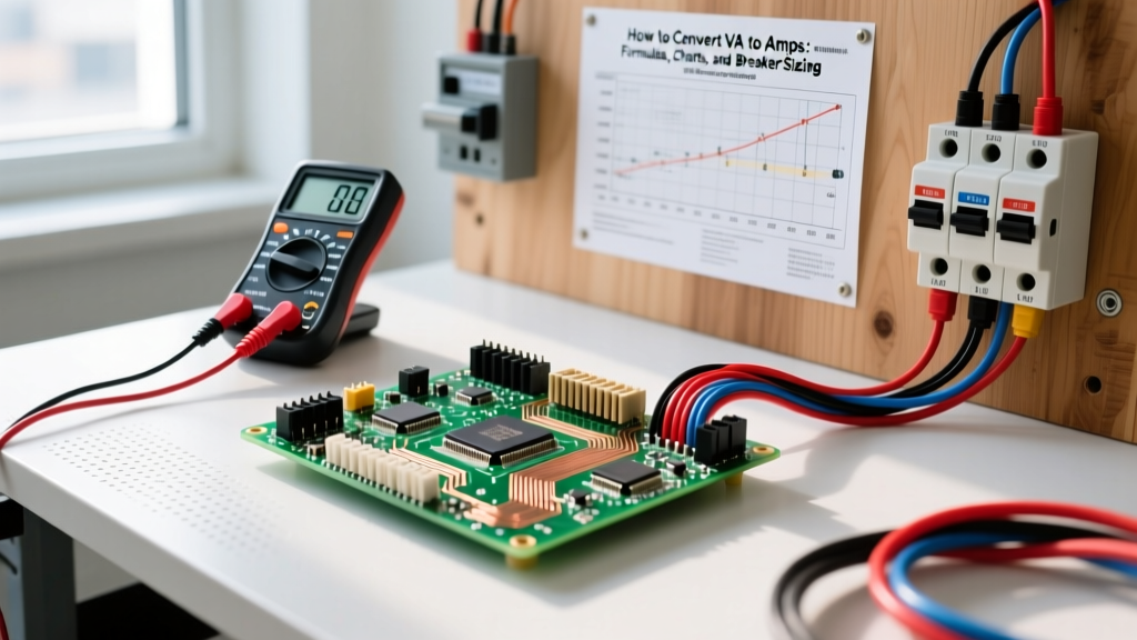
A volt meter measures the electrical potential difference (voltage) between two points in a circuit. In practical terms, what is a volt meter used for? It is the primary diagnostic tool used to verify power presence, measure voltage drop across conductors, check battery state-of-charge, and troubleshoot open or shorted circuits. Whether you are checking if a 120V receptacle is live, verifying a 5V logic rail on an ESP32, or diagnosing a dead 12V automotive battery, the volt meter tells you exactly how much electrical pressure is pushing through your system.
Unlike continuity or resistance tests, voltage measurements are taken on live, energized circuits. This makes proper meter setup, probe technique, and safety categorization critical to both accurate diagnostics and your personal safety.
Meter Setup & Safety Categories (CAT Ratings)
Before touching a single probe to a terminal, your meter must be configured correctly. A misconfigured meter can blow its internal fuse, destroy the circuit under test, or cause an arc flash.
Meter Setup Block
- Lead Jacks: Insert the black lead into the COM (Common) jack. Insert the red lead into the V/Ω (Volts/Ohms) jack. Never leave the red lead in the 'A' or 'mA' (Amps) jack when measuring voltage; this creates a dead short across your test points and will blow the meter's high-energy fuse or cause an explosion.
- Dial Position: Select V~ (or VAC) for alternating current (wall outlets, transformers) or V⎓ (or VDC) for direct current (batteries, solar panels, Arduino logic pins).
- Range: If your meter is manual-ranging, select a range higher than your expected voltage (e.g., select the 20V DC range to test a 12V battery). If auto-ranging, simply select the V function and let the meter's ADC (Analog-to-Digital Converter) lock onto the value.
Step-by-Step Probe Placement for Common Tests
Proper probe placement ensures you are measuring the actual potential difference across the load or source, rather than picking up stray inductive noise. For high-voltage AC work, practice the 'one-hand rule': keep one hand in your pocket or behind your back to prevent current from crossing your chest if a fault occurs.
- AC Receptacle Test (120V): Insert the red probe into the shorter (hot) slot and the black probe into the longer (neutral) slot. To test ground integrity, move the black probe to the U-shaped ground slot; the reading should remain identical (within 0.5V) to the hot-neutral reading.
- DC Battery / Solar Test: Place the red probe firmly on the positive (+) terminal and the black probe on the negative (-) terminal. Ensure probe tips bite through any surface corrosion to make solid metal-to-metal contact.
- PCB / Embedded Logic Test (3.3V or 5V): Use fine-point probes or alligator clips. Place the red probe on the VCC or 5V/3.3V pin header, and the black probe on the GND (ground) plane or pin. Do not rely on USB cable shielding as a guaranteed ground reference for precise logic debugging.
- Voltage Drop Test (Wiring): To find resistance in a wire under load, place the red probe on the source side of the wire and the black probe on the load side. The meter will read the exact voltage 'lost' as heat across that conductor.
Expected Readings: Good vs. Bad Values
A reading of '120V' is rarely exactly 120.0V. According to the ANSI C84.1 standard, utility delivery voltages have specific utilization ranges. Use this spec-sheet-table to evaluate your measurements.
| Test Point | Nominal | Good Range (Acceptable) | Bad / Fault Reading | Likely Cause of Fault |
|---|---|---|---|---|
| US 120V Receptacle | 120V AC | 114V – 126V | < 110V or > 130V | Overloaded branch circuit, loose neutral at panel, or utility tap issue. |
| 240V Dryer/Range Outlet | 240V AC | 228V – 252V | 120V (Hot to Ground on both legs) | Lost leg (open breaker or blown fuse on one phase at the main panel). |
| 12V Lead-Acid Battery (Resting) | 12.6V DC | 12.4V – 12.8V | < 11.9V | Sulfated cell, deep discharge, or parasitic drain overnight. |
| 5V USB / Arduino VCC | 5.0V DC | 4.8V – 5.2V | < 4.5V | Voltage drop across thin USB cable wires or brownout from high current draw. |
| ESP32 3.3V Logic Rail | 3.3V DC | 3.2V – 3.4V | < 3.0V or > 3.6V | Failing onboard LDO regulator or backfeeding 5V into a 3.3V pin. |
Common Mistakes That Give Misleading Readings
When your meter displays a value that defies circuit logic, the issue is usually measurement technique, not a broken law of physics. Watch out for these specific failure modes:
- Testing AC on the DC Range: If you try to measure a wall outlet with the dial set to VDC, the meter's internal filtering will average the sine wave to zero, displaying '0.0V' or erratic jumping numbers. Always match the dial to the current type.
- Low Meter Battery: A dying 9V battery inside your multimeter causes the internal ADC reference voltage to drift. This results in readings that are off by 5% to 15%. If your display shows a low-battery icon, replace it immediately before trusting any diagnostic data.
- Average-Responding vs. True-RMS: If you are measuring the output of a variable frequency drive (VFD), a dimmer switch, or an inverter with a modified sine wave, an 'average-responding' meter will give wildly inaccurate readings. You must use a True-RMS meter to accurately calculate the heating equivalent of non-linear AC waveforms. Read more about waveform measurement on All About Circuits.
Decision Tree: Which Volt Meter Should You Buy?
Choosing the right tool depends on your environment, the waveforms you encounter, and your safety requirements. Use this decision-tree-table to terminate your search and pick the exact model you need.
| If Your Primary Use Case Is... | Required Features | Concrete Pick (2026 Pricing) |
|---|---|---|
| Basic home DIY, 12V automotive, and simple continuity checks. | Auto-ranging, CAT III 600V, basic AC/DC. (True-RMS not strictly required). | Klein Tools MM400 (~$45 USD). Excellent budget entry with robust lead protection. |
| Pro residential/commercial troubleshooting, ghost voltage hunting, and VFDs. | True-RMS, LoZ mode, NCV (Non-Contact Voltage), CAT III 600V / CAT IV 300V. | Fluke 117 Electricians True RMS Multimeter (~$210 USD). The undisputed industry standard for field electricians. |
| Bench electronics, Arduino/ESP32 debugging, and precision sensor calibration. | High precision (4000+ counts), fast refresh rate, milli/micro-amp resolution. (CAT rating irrelevant for <50V bench work). | Brymen BM235 (~$115 USD). Superior DC accuracy and build quality for the electronics workbench. |
The Default Recommendation
If you only buy one meter and need a definitive answer: Buy the Fluke 117. The inclusion of the LoZ (Low Impedance) feature alone will save you hours of chasing ghost voltages in residential switch loops, and its CAT III/IV safety rating ensures you are protected against transients when working inside live subpanels. For pure bench-top embedded electronics where safety categories don't apply and milli-volt precision matters more, default to the Brymen BM235.