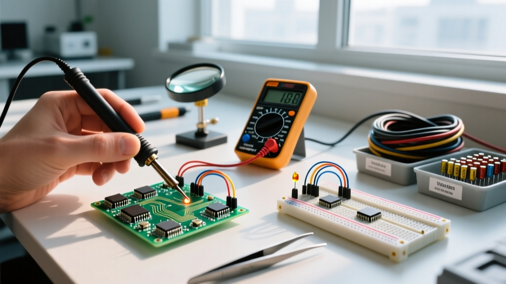
A logic gate is a physical electronic device that implements a Boolean function, taking one or more binary voltage inputs to produce a single binary voltage output. In a real circuit, a logic gate changes continuous, noisy analog voltage levels into discrete, noise-immune digital states (HIGH or LOW), allowing complex hardware decision-making without a microcontroller. Beginners commonly confuse logic gates with microcontrollers or operational amplifiers; unlike an op-amp that outputs a proportional analog voltage, a gate snaps to a hard power rail, and unlike a microcontroller, it executes its function instantaneously in hardware without executing sequential code.
Think of an AND gate like a bank vault with two keys; both the manager's key and the teller's key must be turned simultaneously (both inputs HIGH) for the vault door to open (output HIGH). While modern designs often push these functions into FPGAs or microcontrollers, discrete logic gates remain essential for high-speed glue logic, hardware interlocks, and signal conditioning on the workbench.
The Core Logic Families: TTL vs. CMOS Voltage Thresholds
To use logic gates effectively, you must understand the physical voltage thresholds that define a '1' (HIGH) and a '0' (LOW). These thresholds vary drastically between the two dominant logic families: Transistor-Transistor Logic (TTL) and Complementary Metal-Oxide-Semiconductor (CMOS). Mixing these families on a 5V breadboard without understanding their input thresholds is a classic bench mistake.
| Parameter | 74LS Series (TTL) | 74HC Series (CMOS) | Why It Matters |
|---|---|---|---|
| Supply Voltage (VCC) | 4.75V to 5.25V | 2.0V to 6.0V | CMOS is far more forgiving for battery-powered projects. |
| V_IH (Min HIGH Input) | 2.0V | 3.5V (at 5V VCC) | A 3.3V microcontroller GPIO cannot reliably drive a 5V 74HC input HIGH. |
| V_IL (Max LOW Input) | 0.8V | 1.5V (at 5V VCC) | TTL is more susceptible to noise on the LOW state. |
| Input Impedance | Low (kΩ range) | Extremely High (>10^12 Ω) | CMOS inputs will float and cause erratic behavior if left unconnected. |
According to the SparkFun Logic Gates Tutorial, the most common interoperability failure occurs when a 3.3V ESP32 tries to drive a 5V 74HC08 AND gate. Because the 74HC family requires 3.5V minimum to register a HIGH, the ESP32's 3.3V output falls in the undefined region, resulting in random output toggling. The fix is to use a 74HCT series IC, which combines CMOS power efficiency with TTL-compatible input thresholds (V_IH = 2.0V).
Worked Numeric Example: Calculating Dynamic Power Dissipation
When designing a battery-operated sensor node, you need to know exactly how much current your glue logic will draw. Let's calculate the power dissipation of a single gate inside a 74HC00 (Quad 2-Input NAND) running at 5V and switching a 10 MHz clock signal.
- Identify Quiescent Power: The datasheet specifies a maximum quiescent supply current (I_CC) of 20 µA per gate. At 5V, this static power is negligible (100 µW).
- Find Power Dissipation Capacitance (C_pd): For the 74HC00, C_pd is typically 18 pF. This represents the internal parasitic capacitance that must be charged and discharged every time the gate switches.
- Apply the Dynamic Power Formula: P_dynamic = C_pd × V_CC² × f.
- Calculate: P = 18 × 10^-12 F × (5V)² × 10,000,000 Hz.
- Result: P = 18pF × 25V² × 10^7 = 4.5 mW per gate.
While 4.5 mW seems trivial, if you are buffering a 32-bit data bus running at 50 MHz using multiple 74HC245 transceivers, that dynamic switching current scales linearly with frequency and bus width, easily pushing your logic ICs into thermal throttling or draining a coin cell in hours. For high-frequency, low-power applications, you would pivot to the 74LVC or 74AUP families, which operate at lower voltages (reducing the V² multiplier) and feature smaller C_pd values.
Where You Meet Logic Gates in Practice
While it is tempting to route every signal into a microcontroller and handle it in software, hardware logic gates solve specific physical problems that software cannot touch. Here is where you will reach for a discrete logic IC on the bench:
- Hardware Debouncing: Mechanical switches bounce for 5-50ms when pressed. Instead of wasting CPU cycles polling a pin, an SR latch built from two NAND gates (like a CD4011) physically locks the output state the microsecond the switch makes contact, providing a perfectly clean digital edge to your microcontroller's interrupt pin.
- Safety Interlocks: In industrial motor control, emergency stop (E-Stop) circuits must not rely on software. A hardwired AND gate ensures that the motor contactor coil is only energized if the E-Stop is closed AND the safety guard door is shut. If the PLC crashes, the hardware gate still cuts the power.
- Signal Gating and Multiplexing: If you need to pass a high-frequency PWM signal to a load only when an enable pin is HIGH, an AND gate acts as a hardware switch. Software toggling introduces jitter; an AND gate passes the PWM with a mere nanosecond propagation delay.
- Level Shifting: Dedicated logic gates like the 74LVC1T45 are used specifically to translate logic levels between a 1.8V sensor and a 3.3V microcontroller without the voltage drop associated with simple resistor dividers.
Real-World Scenario Walkthrough: The Floating Input Disaster
The Numbers: The limit switch is mounted 4 feet away from the breadboard, connected via unshielded 22 AWG wire. The 74HC08 has an input impedance of >10^12 Ω. The V_IH threshold is 3.5V.
The Outcome: When the window is open (limit switch open), Input A is disconnected from GND. The motor randomly turns on and off, slamming the window against the frame, even though the moisture sensor (Input B) is outputting a steady LOW.
What Went Wrong: Because the CMOS input impedance is practically infinite, the 4-foot unshielded wire on Input A acted as an antenna. It picked up 60Hz electromagnetic interference from nearby AC mains wiring. The voltage on the floating pin oscillated wildly between 0V and 5V. Whenever the induced noise spiked above the 3.5V V_IH threshold, the AND gate registered a HIGH. Worse, when the noise held the input voltage in the linear region (around 2.5V), both the internal PMOS and NMOS transistors of the gate turned on simultaneously. This 'shoot-through' current caused the 74HC08 IC to overheat, drawing 15 mA of wasted current per floating pin instead of microamps.
The Fix: Never leave a CMOS input floating. The builder added a 10kΩ pull-down resistor from Input A to GND. This provided a definitive LOW state when the switch was open, shunting the induced 60Hz noise to ground and stabilizing the circuit. As noted in the All About Circuits Digital Logic textbook, tying unused or switched inputs to a defined rail via a resistor is mandatory for CMOS reliability.
Frequently Asked Questions
Can I just use an Arduino or ESP32 instead of discrete logic gates?
You can, but you trade speed and determinism for convenience. A microcontroller reads an input, processes the logic, and writes an output in a few microseconds, subject to interrupt latency and code execution time. A 74-series logic gate completes the same operation in roughly 8 nanoseconds. If you are debouncing a button or blinking an LED, use the microcontroller. If you are gating a 20 MHz clock signal or building a fail-safe hardware kill switch, use discrete logic gates.
What happens if I exceed the maximum fan-out of a gate?
Fan-out is the number of standard inputs a single gate output can reliably drive. For a 74HC gate driving other 74HC inputs, the DC fan-out is virtually unlimited (often >1000) because CMOS inputs draw almost zero steady-state current. However, the AC fan-out is limited by capacitance. Every input you connect adds roughly 3 to 5 pF of parasitic capacitance to the output pin. If you connect 20 inputs to a single output, you add ~80 pF of load. This creates an RC low-pass filter with the gate's output resistance, rounding off the sharp digital square wave edges, increasing propagation delay, and potentially causing the receiving gates to trigger multiple times on a single slow-moving edge.