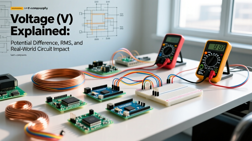

Voltage (V), also known as electric potential difference, is the measurable force that pushes electrons through a conductive path, measured in volts. It is the fundamental pressure in any electrical system, dictating how much current will flow through a given resistance and determining the insulation thickness required to keep that energy safely contained within the wire.
The Core Definition and Common Confusions
In a real circuit, altering the voltage V changes the current draw (per Ohm's Law, I = V/R) and the total power dissipated (P = V × I). In a physical installation, higher voltage demands greater dielectric strength in wire insulation and wider physical clearance in busbars to prevent arcing. If you double the voltage across a fixed resistor, the current doubles, but the power dissipated as heat quadruples—a reality that routinely melts under-sized components on the workbench.
Beginners routinely confuse voltage (V) with current (Amps) and power (Watts). Voltage is the potential to do work; current is the actual flow of electrons; power is the rate at which work is completed. To ground this in physics, use the water analogy exactly once: think of a pressurized water tank connected to a hose. Voltage is the water pressure inside the tank. Current is the gallons-per-minute flowing through the hose. Power is the total volume of water delivered over time. If the tank is elevated on a tower (high voltage) but the valve is closed (an open circuit), you have high pressure but zero flow.
Nominal vs. Measured Voltage (V) in Real Systems
One of the most common mistakes hobbyists make is treating printed voltage labels as exact physical realities. '120V' or '12V' are nominal designations, not strict guarantees. Grid voltage fluctuates based on transformer tap settings, line loading, and distance from the substation. Similarly, battery voltage shifts dramatically based on state of charge (SoC), internal resistance, and temperature. According to the NFPA 70 National Electrical Code and utility standards, equipment must be designed to tolerate a specific bandwidth of voltage variance without failing.
| System Type | Nominal Label | Actual Measured Range | Tolerance Standard / Notes |
|---|---|---|---|
| US Residential Split-Phase | 120V AC | 114V - 126V | ANSI C84.1 Range A (Utility target) |
| US Residential Split-Phase | 240V AC | 228V - 252V | ANSI C84.1 Range A (Heavy appliance feed) |
| 12V Lead-Acid Battery | 12.0V DC | 12.6V - 12.8V (Resting) | Fully charged state; drops to ~11.8V under load |
| 12V LiFePO4 Battery | 12.8V DC | 13.2V - 13.6V (Resting) | BMS low-voltage cutoff typically triggers at 10.0V |
| ESP32 / ARM Microcontroller | 3.3V Logic | 3.2V - 3.4V | Exceeding 3.6V risks permanent gate oxide breakdown |
Worked Example: How Voltage (V) Drop Alters Circuit Performance
To see how voltage V behaves under load, let's calculate a real-world DC voltage drop scenario. Assume you are wiring a 12V DC off-grid solar setup to power a 15A diaphragm water pump located 10 feet from your battery bank.
- Source: 12V nominal LiFePO4 battery (actually resting at 13.4V).
- Load: 15A DC water pump.
- Wire: 12 AWG copper. Total loop length is 20 feet (10 ft positive, 10 ft negative return).
According to standard copper wire tables, 12 AWG wire has a resistance of roughly 1.588 ohms per 1,000 feet. For our 20-foot total loop, the resistance (R) is 0.03176 ohms.
Calculating the Drop:
V_drop = I × R
V_drop = 15A × 0.03176 Ω = 0.476V
Voltage at the Load:
13.4V (Source) - 0.476V (Drop) = 12.92V
The pump receives 12.92V and operates perfectly. Now, imagine you decided to save money and used 16 AWG wire instead. The resistance jumps to 4.016 ohms per 1,000 feet, making our 20-foot loop 0.08032 ohms. The new voltage drop is 15A × 0.08032 Ω = 1.20V. The pump now only sees 12.2V. Because DC motors attempt to maintain mechanical output by drawing more current when voltage sags, this 1.2V drop can cause the pump to pull 18A, overheating the 16 AWG wire and potentially tripping the battery's BMS on a low-voltage fault. This is why calculating voltage V drop is mandatory for low-voltage DC systems.
Where You Meet Voltage (V) in Practice
Understanding potential difference is not just academic; it dictates your material choices and safety protocols across three major domains of electrical work.
1. Mains AC Wiring and RMS vs. Peak
When you measure a standard US wall outlet, your multimeter reads roughly 120V AC. This is the Root Mean Square (RMS) value—the equivalent DC voltage that would produce the same heating effect in a resistor. However, the actual sine wave peaks at roughly 170V (120V × √2). This is why the NEC mandates 600V-rated THHN insulation for standard 120V/240V branch circuits. The dielectric insulation must comfortably handle the peak voltage plus transient inductive spikes from motors switching off, not just the RMS average. For deeper theory on AC waveforms, All About Circuits provides an excellent breakdown of RMS calculations.
2. Microcontrollers and Logic Level Translation
In embedded systems, voltage V defines the logic threshold. An Arduino Uno (ATmega328P) operates at 5V logic, meaning it expects ~5V on a GPIO pin to read a digital 'HIGH'. An ESP32 or Raspberry Pi Pico operates at 3.3V logic. If you connect a 5V sensor output directly to an ESP32 GPIO pin, you are not just 'pushing harder'—you are forcing 5V through a silicon junction rated for a maximum of 3.6V. This breaches the gate oxide layer, permanently shorting the pin to VCC and bricking the microcontroller. You must use a logic level converter or a voltage divider to step the 5V signal down to a safe 3.3V.
3. Battery Banks and Series vs. Parallel
When building LiFePO4 or 18650 lithium-ion packs, voltage V determines your system architecture. Wiring four 12V 100Ah batteries in parallel keeps the system at 12V but yields 400Ah of capacity. Wiring those same four batteries in series creates a 48V 100Ah bank. The 48V system is vastly superior for high-power applications (like a 3000W inverter) because it cuts the current draw by 75% compared to the 12V system, allowing you to use much smaller, cheaper copper wire and reducing I²R heat losses.
Frequently Asked Questions
Why is my multimeter reading 125V on a standard 120V outlet?
This is completely normal and well within utility tolerances. Under the ANSI C84.1 standard, utilities are required to deliver voltage within Range A (114V to 126V for a 120V nominal system). If you live close to the utility transformer and there is little load on the local grid, the voltage will sit at the higher end of that band. Modern electronics and appliances are designed with internal switching power supplies that easily handle 125V without damage.
Can I use a 240V-rated breaker on a 120V circuit?
Yes. The voltage rating stamped on a breaker (e.g., 120/240V or 240V max) is a maximum ceiling, indicating the highest potential difference the breaker's internal arc chute can safely extinguish. Using a 240V breaker on a 120V circuit is electrically safe, though it is usually a waste of money and panel space. However, you cannot use a 120V-rated breaker on a 240V circuit, as the arc from a short circuit would not be contained, leading to a catastrophic panel failure.
Does voltage drop matter for short 5V USB cables?
Absolutely. If you are powering a 5V 2A Raspberry Pi 4 through a cheap, thin 28 AWG USB-C cable that is 6 feet long, the resistance of the wire will cause a significant voltage V drop. The Pi might only see 4.6V at its input, triggering the infamous 'low voltage warning' rainbow square on the screen and causing random brownouts and SD card corruption. Always use thick, high-quality cables (20 AWG or thicker for power lines) for low-voltage, high-current DC runs.


