When selecting or replacing voltage capacitors, the golden rule is that the replacement's voltage rating must be equal to or higher than the original, while the capacitance (µF, nF, pF) must match exactly or fall within the circuit's tolerance (typically ±10% to ±20%). A 16V capacitor cannot safely replace a 25V capacitor, but a 50V capacitor can replace a 25V one, provided physical size, Equivalent Series Resistance (ESR), and dielectric absorption constraints are met. This guide breaks down how to read physical markings, select the right chemistry for the job, diagnose failures, and substitute parts safely when your exact BOM component is out of stock.
Decoding Voltage Capacitor Markings and Codes
Manufacturers use different marking standards depending on the capacitor's physical size and chemistry. Misreading these codes is the most common cause of accidental overvoltage failures on the bench.
Electrolytic and Tantalum (Direct Printing)
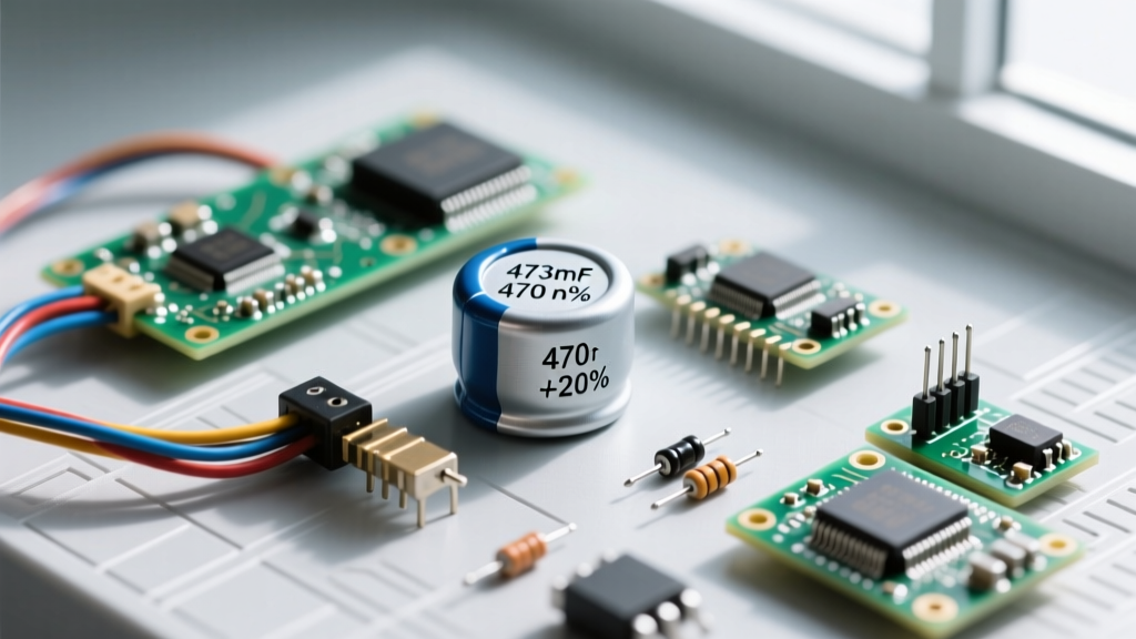
Through-hole and large SMD aluminum electrolytics print values directly: 470µF 25V. The voltage rating is explicit. Polarity is indicated by a contrasting stripe on the cylinder; for aluminum electrolytics, this stripe marks the cathode (negative) lead. For tantalum beads, the printed line or bar marks the anode (positive) lead. Reversing these will cause catastrophic failure.
Ceramic and Film (EIA 3-Digit Codes)
Small ceramic and film voltage capacitors use the EIA 3-digit code for capacitance, measured in picofarads (pF). The first two digits are the significant figures, and the third is the multiplier (number of zeros).
- Example: A marking of
104means 10 × 104 pF = 100,000 pF = 100 nF = 0.1 µF. - Tolerance: A trailing letter indicates tolerance.
104Kmeans 0.1µF ±10%.104Jis ±5%, and104Mis ±20%.
Voltage Letter Codes (SMD and Miniature Ceramics)
While standard 5mm through-hole ceramics often assume a 50V rating if unmarked, SMD and specialized voltage capacitors use a two-character EIA voltage code. The first character is a multiplier, the second is the base voltage.
| Code | Voltage Rating | Code | Voltage Rating |
|---|---|---|---|
| 0J | 6.3V | 1E | 25V |
| 1A | 10V | 1H | 50V |
| 1C | 16V | 2A | 100V |
Type Comparison: Which Voltage Capacitor for Which Job?
Capacitance and voltage are only half the story. The dielectric material dictates the capacitor's behavior under temperature swings, ripple current, and high frequencies. Here is the selection framework for common voltage capacitors.
| Type | Construction / Dielectric | Tolerance | Tempco / ESR Traits | Typical Use Case |
|---|---|---|---|---|
| Aluminum Electrolytic | Etched foil, liquid/polymer electrolyte | ±20% | High ESR, poor high-freq response, dries out at 105°C | Bulk power filtering, low-freq coupling |
| Tantalum (MnO2) | Porous tantalum anode, MnO2 cathode | ±10% to ±20% | Stable capacitance, moderate ESR, fails short (fire risk) | Compact DC decoupling, medical/aerospace (with derating) |
| MLCC (X7R / X5R) | Multi-layer ceramic (barium titanate) | ±10% to ±20% | Very low ESR, high capacitance drop under DC bias | High-freq decoupling, SMPS output filtering |
| MLCC (C0G / NP0) | Multi-layer ceramic (para-electric) | ±1% to ±5% | Zero tempco, no DC bias drop, piezoelectric-free | RF matching, precision timing, audio signal paths |
| Polypropylene Film | Metallized polypropylene film (e.g., WIMA MKP10) | ±1% to ±5% | Extremely low dielectric absorption, self-healing | Audio crossovers, snubber circuits, high-voltage AC |
Selection Insight: If you are designing a switching power supply (SMPS), you must use Low-ESR aluminum electrolytics (like the Panasonic FR or FM series) or MLCCs on the output. Standard electrolytics will overheat and vent due to high ripple current. For precision analog audio, avoid X7R ceramics in the signal path; their piezoelectric nature introduces microphonic noise and voltage-dependent distortion. Use C0G/NP0 or polypropylene instead.
Failure Modes and Visual Symptoms
Voltage capacitors fail in distinct ways depending on their chemistry. Recognizing these symptoms saves hours of troubleshooting.
- Aluminum Electrolytic (Venting/Drying): The most common failure. Visually, the top cross-scored dome bulges upward, or brown electrolyte crust leaks from the bottom rubber bung. Hidden failure: The capacitor looks perfect but ESR has drifted above 1 ohm (measured at 100kHz). It passes a DC multimeter test but fails under AC ripple load.
- Tantalum (Thermal Runaway): MnO2 tantalums fail as a dead short. If the power supply can deliver enough current, the MnO2 dielectric converts to a lower oxide, releasing oxygen and causing literal fire and smoke. Visually: a charred, cracked, or completely missing beige/black bead on the PCB.
- MLCC Ceramic (Mechanical Cracking): MLCCs are brittle. Board flex during depanelization or connector insertion causes microscopic cracks that propagate, leading to intermittent or dead shorts. Visually invisible without X-ray or cross-sectioning, but often located near mounting holes or heavy connectors.
- Film Capacitors (Self-Healing): Metallized film capacitors experience internal micro-arcs that vaporize the metallization around the fault, isolating it. The capacitor survives, but total capacitance drops slightly over time. External failure only occurs if subjected to massive overvoltage, resulting in a split or melted plastic casing.
Safe Substitution Rules When the Exact Part is Missing
When your exact BOM part is obsolete or out of stock, follow these substitution rules to maintain circuit integrity without compromising safety.
1. Voltage Ratings: Always Go Up
You can always substitute a higher voltage capacitor for a lower one (e.g., using a 50V part in a 25V circuit). However, higher voltage parts are physically larger and may have higher ESR or lower ripple current ratings. Never substitute a lower voltage rating, even if the circuit's nominal voltage seems lower than the original cap's rating; transient spikes will destroy it.
2. Capacitance and Tolerance
For bulk DC filtering, a ±20% deviation is acceptable, and going up 20-30% in capacitance is usually fine (though it may increase inrush current). For timing circuits (555 timers, oscillators) or active filters, you must match the exact capacitance and use tight tolerance (±1% to ±5%) parts.
3. ESR and Ripple Current
A Low-ESR capacitor can generally replace a standard-ESR capacitor. The reverse is fatal in switching regulators. If replacing an electrolytic, check the datasheet for the 105°C / 100kHz ESR spec. Do not substitute a standard 85°C cap for a 105°C cap in a hot environment, as the lifespan halves for every 10°C increase in ambient temperature.
If you are repairing a power supply and the capacitor bridges the AC mains line (Line-to-Line or Line-to-Ground), you must use X2 or Y2 safety-rated voltage capacitors certified to IEC 60384-14. Standard film or ceramic capacitors will fail dangerously under mains transients. X2 capacitors are designed to fail short (blowing the upstream fuse), while Y2 capacitors fail open to prevent chassis electrocution. See Digi-Key's technical breakdown of safety capacitors for class specifications. Never substitute standard parts here.
Frequently Asked Questions About Voltage Capacitors
Can I use a higher voltage capacitor instead of the original?
Yes, electrically it is perfectly safe. A 50V capacitor in a 12V circuit will experience less dielectric stress, potentially increasing its lifespan. The practical limitations are physical footprint (it might not fit the PCB pads or enclosure) and electrical characteristics. In some high-frequency circuits, a physically larger high-voltage MLCC will have higher parasitic inductance (ESL), which can degrade decoupling performance.
Why do my MLCC ceramic voltage capacitors sing or whine?
This is caused by the piezoelectric effect inherent in Class II dielectrics (X7R, X5R). When subjected to AC ripple or switching frequencies in the audible range (20Hz - 20kHz), the ceramic physically vibrates, acting as a tiny speaker. To fix this, you can switch to a larger case size (which shifts the resonant frequency), use a polymer or electrolytic capacitor for the bulk filtering, or use an interleaved PCB layout to cancel out the mechanical stress. For critical audio paths, switch to C0G/NP0 ceramics which are not piezoelectric.
How do I safely discharge high voltage capacitors before working on them?
Never short a high-voltage capacitor (like those in microwave ovens, CRT monitors, or camera flashes) with a metal screwdriver. The instantaneous current can weld the tool, destroy the capacitor's internal connections, and shower you with molten metal. Always use a high-wattage bleeder resistor (e.g., a 10kΩ to 100kΩ, 5W+ resistor) attached to insulated probes. Connect it across the terminals for several seconds, then verify the voltage is below 50V DC using a properly rated digital multimeter before touching the circuit. For further reading on electrolytic behavior and discharge curves, refer to Cornell Dubilier's Aluminum Electrolytic Application Guide.
Does capacitor polarity matter in AC coupling circuits?
If the signal is purely AC with no DC bias, you must use a non-polarized capacitor (film, ceramic, or specifically manufactured non-polar electrolytic). If you must use a polarized aluminum electrolytic for a large value in an audio coupling application, you can create a 'back-to-back' non-polar configuration by placing two identical polarized electrolytics in series with their negative terminals tied together. However, this halves the total capacitance and doubles the ESR, so film capacitors are strongly preferred for audio signal paths.