Inductive reactance is the opposition an inductor presents to alternating current (AC), measured in ohms (Ω), while the underlying physical property of inductance itself is measured in henrys (H). If you are searching for the 'unit of inductance reactance,' you are likely conflating two related but distinct concepts: the component's physical capacity to store magnetic energy (inductance) and its resulting resistance to AC flow (reactance). Understanding the boundary between henrys and ohms is critical for anyone designing filters, sizing motor windings, or troubleshooting switch-mode power supplies.
The Core Distinction: Henrys vs. Ohms
To clear up the terminology immediately: inductance is a physical property of a component, determined by its core material, number of wire turns, and coil geometry. It does not change based on the frequency of the signal passing through it. Inductive reactance, however, is a behavioral effect. It is the actual impedance the inductor throws up against AC current, and it scales linearly with frequency.
| Property | Symbol | Unit | Depends on Frequency? | Measured With |
|---|---|---|---|---|
| Inductance | L | Henrys (H, mH, μH) | No | LCR Meter (at a fixed test freq) |
| Inductive Reactance | XL | Ohms (Ω) | Yes (Linear) | Calculated or derived via V/I in AC |
The Math: Calculating Inductive Reactance
The formula that bridges the physical unit (henrys) to the circuit effect (ohms) is straightforward:
XL = 2πfL
Where f is the frequency in Hertz and L is the inductance in Henrys.
Worked Numeric Example
Suppose you are building a passive low-pass filter for a 60 Hz mains hum and you select a 150 mH (0.15 H) iron-core choke. What is its actual opposition to the 60 Hz AC line?
- XL = 2 × 3.14159 × 60 Hz × 0.15 H
- XL = 56.55 Ω
What this changes in a real circuit: Unlike a 56-ohm resistor, which would burn off power as heat (I²R losses), this inductor limits the 60 Hz current by temporarily storing energy in a magnetic field and returning it to the circuit. It also introduces a phase shift, causing the current to lag the voltage by up to 90 degrees, which alters your power factor but wastes virtually zero real power.
Where You Meet This in Practice
You will encounter the interplay between henrys and ohms in several common electrical and electronic scenarios:
- HVAC Compressor Motors: The start and run windings have high inductance. At 60 Hz, this creates significant inductive reactance, which is why motor nameplates specify a 'Locked Rotor Amps' (LRA) and why you need run capacitors to cancel out that reactance and improve the power factor.
- Switch-Mode Power Supplies (SMPS): In a buck converter switching at 500 kHz, a tiny 4.7 μH inductor presents a massive reactance to the high-frequency switching node, smoothing the current into a steady DC output.
- Audio Crossover Networks: A woofer's voice coil has inherent inductance. As audio frequencies rise, the inductive reactance increases, naturally rolling off the high frequencies before they can damage the speaker.
Bench War Story: When Ignoring Reactance Burns a Circuit
Theory is clean; the workbench is not. Here is a real-world scenario where miscalculating the unit of inductive reactance led to catastrophic component failure.
The Setup
I was prototyping a 12V DC to 120V AC pure sine wave inverter using an ESP32 for SPWM (Sinusoidal Pulse Width Modulation) generation. To smooth the high-frequency PWM into a clean 60 Hz sine wave, I placed a 2.2 mH toroidal inductor on the AC output, followed by a 10 μF film capacitor.
The Numbers
I only calculated the reactance for the fundamental 60 Hz output frequency:
XL = 2π × 60 × 0.0022 = 0.83 Ω.
At a planned 10A load, the voltage drop across the inductor would be a negligible 8.3V. The math looked perfect.
The Outcome
Upon applying power, the inverter ran for exactly three seconds before both IRFP460 MOSFETs in the H-bridge shorted violently and vented magic smoke.
What Went Wrong
I had forgotten that the SPWM switching frequency was 20 kHz. While the inductor's physical value remained 2.2 mH, its reactance at the switching frequency was entirely different:
XL = 2π × 20,000 × 0.0022 = 276.4 Ω.
The inductor choked the 20 kHz harmonics so aggressively that it generated massive voltage spikes (inductive kickback) during the MOSFET switching transitions. These spikes easily exceeded the 500V VDS rating of the IRFP460s. The fix required adding an RC snubber network across the MOSFETs and recalculating the LC filter to properly attenuate the 20 kHz carrier without saturating the toroid core.
Common Confusions: Reactance vs. Resistance
Beginners frequently confuse inductive reactance (Ω) with DC resistance (Ω). While both are measured in ohms and both limit current, their physical mechanisms are entirely different. According to HyperPhysics, resistance is the collision of electrons with the atomic lattice of a conductor, generating heat. Reactance is the opposition to the change in current, governed by Faraday's law of induction. Furthermore, a common pitfall is assuming an inductor's DC resistance (DCR) dictates its AC behavior. A massive 500 mH inductor might have a DCR of just 0.5 Ω, but at 10 kHz, its reactance will be over 31,000 Ω.
Frequently Asked Questions
Is impedance the same as inductive reactance?
No. Impedance (Z) is the total opposition to AC current, combining both resistance (R) and reactance (X) vectorially. In a real-world inductor, you must account for the wire's DC resistance and the core losses. The formula is Z = √(R² + XL²). For high-quality inductors where XL is much larger than R, impedance and reactance are nearly identical.
Does inductive reactance affect DC circuits?
Only during transient states (the exact moment power is turned on or off). Because the formula XL = 2πfL relies on frequency, and DC frequency is 0 Hz, the steady-state inductive reactance to pure DC is zero ohms. The only opposition to steady DC is the wire's physical resistance (DCR).
How do I measure inductive reactance with a multimeter?
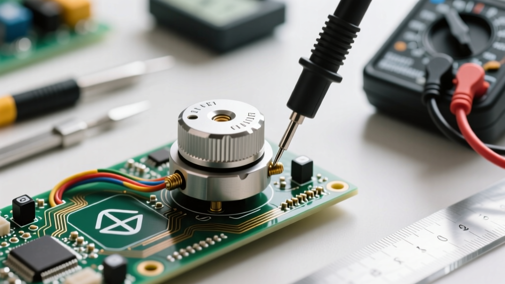
You cannot measure it directly with a standard multimeter. A multimeter's ohms setting injects a tiny DC current to measure resistance. To find reactance, you must either measure the inductance (henrys) using a dedicated LCR meter and calculate the reactance for your specific frequency, or apply a known AC voltage, measure the resulting AC current, and use Ohm's law (XL = V/I), as detailed in All About Circuits.