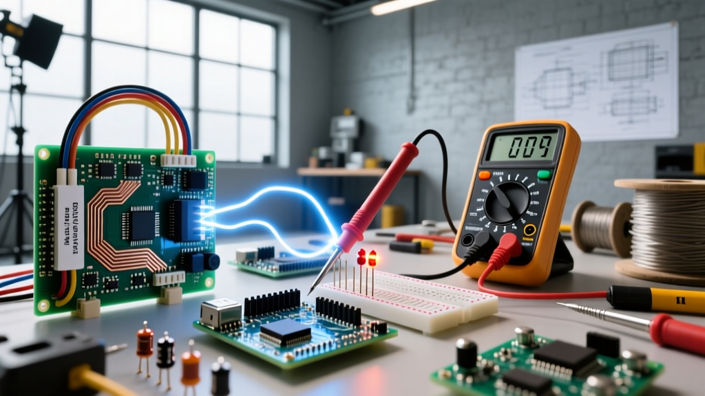
The unit of measurement of resistance is the ohm, symbolized by the Greek letter omega (Ω). Named after physicist Georg Simon Ohm, it quantifies how much a material opposes the flow of electrical current. By definition, one ohm is the resistance that allows exactly one ampere of current to flow when one volt of potential difference is applied across it (V = IR). In practical bench and jobsite work, you will rarely measure just one ohm; instead, you will navigate milliohms (mΩ), kilohms (kΩ), and megohms (MΩ) depending on the component.
The Metric Prefixes: Scaling the Ohm
Because electrical circuits span everything from heavy-duty heating elements to microscopic silicon pathways, the base ohm is scaled using standard metric prefixes. Understanding these multipliers is critical for reading datasheets and interpreting multimeter displays without making decimal errors.
- Milliohms (mΩ): 0.001 Ω. Used for measuring current shunts, thick busbars, and the internal DC resistance (DCR) of transformer windings.
- Ohms (Ω): The base unit. Typical for speaker voice coils, incandescent bulb filaments, and power resistors.
- Kilohms (kΩ): 1,000 Ω. The standard range for signal-level components like pull-up resistors, voltage divider networks, and transistor bias resistors.
- Megohms (MΩ): 1,000,000 Ω. Used for insulation testing, high-impedance sensor inputs, and bleeder resistors in power supplies.
For a deeper look at how these values interact with voltage and current, review the foundational Ohm's Law chapter on All About Circuits.
Meter Setup & Probe Placement for Resistance Testing
Measuring resistance requires the multimeter to output a small, known test current and measure the resulting voltage drop. If your meter is configured incorrectly, you will get garbage data or blow an internal fuse.
Meter Setup Block
- Dial Position: Turn the rotary switch to the Ω symbol. Do not use the continuity/diode setting if you need a precise numerical value, as that mode only provides a binary pass/fail beep or a forward voltage drop reading.
- Lead Jacks: Insert the black lead into the COM (common) jack. Insert the red lead into the VΩ (or VΩmA) jack. Never leave the red lead in the 10A high-current jack when measuring resistance; the low shunt resistance of that jack will skew your reading to near zero.
- Range Selection: If using a manual-ranging meter, start at the highest range (e.g., 20MΩ) and step down until you get the most significant digits without the display flashing 'OL' (Over Limit). Auto-ranging meters handle this internally but may take 1-2 seconds to settle on high-resistance values.
Probe Placement and Safety
Resistance must always be measured on a de-energized circuit. The component should ideally be isolated (at least one leg lifted from the PCB) to prevent parallel circuit paths from skewing the reading. Place the probe tips directly on the metal leads or solder pads of the component. For standard resistors, polarity does not matter; the reading will be identical regardless of which probe touches which leg.
Expected Readings: Good vs. Bad Component Values
A 'good' reading numerically falls within the manufacturer's stated tolerance (usually ±1%, ±5%, or ±10% of the nominal value). A 'bad' reading typically manifests as an open circuit ('OL') or a dead short (0.0 Ω), though components can also drift out of tolerance due to thermal stress.
| Component Type | Nominal Value | Good Reading (Expected Range) | Bad Reading (Failure Mode) |
|---|---|---|---|
| 10kΩ Pull-up Resistor (5%) | 10,000 Ω | 9,500 Ω to 10,500 Ω | 'OL' (burned open) or >12kΩ (drifted) |
| 8Ω Speaker Voice Coil | 8.0 Ω | 6.5 Ω to 7.8 Ω (DCR is lower than AC impedance) | 'OL' (tinsel wire broken) or <1.0 Ω (shorted windings) |
| 1MΩ Capacitor Bleeder Resistor | 1,000,000 Ω | 950kΩ to 1.05MΩ | 'OL' (failed open, creating a shock hazard) |
| 120V 1500W Space Heater Element | ~9.6 Ω (Calculated via R = V²/P) | 9.0 Ω to 10.5 Ω (cold resistance) | 'OL' (nichrome wire snapped internally) |
Common Mistakes That Give Misleading Readings
If your multimeter is displaying numbers that defy Ohm's Law, you are likely falling victim to one of these bench-level errors:
- Measuring In-Circuit (Parallel Paths): If you measure a 10kΩ resistor while it is still soldered into a PCB, the meter's test current will flow through parallel semiconductor junctions and other resistors. This will always result in a reading lower than the actual component value. Lift one leg of the component to isolate it.
- The 'Human Resistor' Effect: When measuring values above 100kΩ, touching the metal probe tips or the bare component leads with your fingers introduces your body's resistance (typically 10kΩ to 100kΩ depending on skin moisture) in parallel with the component. Hold the probes by the insulated grips only.
- Ignoring Test Lead Resistance: Standard multimeter leads have about 0.2Ω to 0.5Ω of internal resistance. If you are trying to measure a 0.1Ω current shunt, your meter will read 0.4Ω. For sub-1Ω measurements, short the probe tips together, note the lead resistance, and subtract it from your final reading (or use a 4-wire Kelvin measurement setup).
- Oxidized Leads and Dirty Contacts: Flux residue, corrosion, or oxidation on component leads acts as a series resistor. Scrape the probe tip against the lead to break through the oxide layer before taking the final reading.
Frequently Asked Questions
What is the unit of measurement of resistance in a series circuit?
The unit remains the ohm (Ω). In a series circuit, the total resistance is simply the sum of the individual resistances (R_total = R1 + R2 + R3...). If you place three 100Ω resistors in series, the total unit measurement is still ohms, but the numerical value becomes 300Ω.
Why does my multimeter show 'OL' when measuring resistance?
'OL' stands for Over Limit (or Open Loop on some older meters). It means the resistance between the two probe tips is higher than the maximum range the meter can measure (typically >20MΩ or >40MΩ). In practical terms, this indicates an open circuit: a blown fuse, a broken wire, a snapped heating element, or a switch that is in the 'OFF' position.
Can I measure the resistance of a capacitor or inductor?
You can, but you must understand what you are actually measuring. A multimeter in ohms mode measures DC resistance (DCR), not AC reactance. A healthy capacitor will initially show a low resistance as it charges from the meter's test current, then quickly climb to 'OL' (open). A healthy inductor (like a motor winding or transformer coil) will simply read its wire resistance, which is usually a very low number (e.g., 0.5Ω to 5.0Ω).
What is the difference between resistance and continuity?
Continuity is a binary, qualitative test. The meter sends a small current and beeps if the resistance is below a specific threshold (usually between 10Ω and 30Ω), telling you a connection exists. Resistance is a quantitative measurement that gives you the exact numerical opposition to current flow in ohms, allowing you to verify if a component is within its specified tolerance.