Biased current is the steady DC current flowing through a component—most commonly an inductor or transformer—that shifts its internal magnetic or semiconductor operating point, fundamentally altering its effective impedance or quiescent state. When you design a buck converter, an MPPT solar charge controller, or a Class-A audio amplifier, ignoring this parameter will result in a melted MOSFET, a smoking inductor, or severe crossover distortion. In power electronics, biased current dictates the magnetic saturation limit; in semiconductors, it establishes the baseline for signal amplification.
The Core Physics: How DC Biased Current Alters Inductance
To understand what biased current changes in a real circuit, we have to look at the B-H curve (magnetic flux density vs. magnetic field strength) of an inductor's core material. When DC current flows through an inductor's windings, it generates a static magnetic field. This DC biased current shifts the operating point away from the origin of the B-H curve and pushes it toward the 'knee' of saturation.
Think of a magnetic core like a sponge soaking up water. Initially, the dry sponge absorbs water easily, representing high magnetic permeability and stable inductance. But once the sponge is fully saturated, it cannot hold any more water; additional liquid just spills over the sides. In magnetics, the 'water' is the magnetic flux generated by your biased current. Once the core saturates, the permeability drops toward the permeability of free air, and the inductance collapses.
Worked Numeric Example: The 10 µH Buck Converter Trap
Let's look at a standard 10 µH shielded ferrite power inductor (similar to a Coilcraft MSS1210 series). At 0A DC bias, your LCR meter reads exactly 10 µH. The datasheet specifies a 30% inductance drop at 4.5A of DC biased current.
If your 12V-to-5V buck converter is designed to deliver a continuous 4.5A load to a Raspberry Pi cluster, your '10 µH' inductor is now physically acting as a 7 µH inductor in the circuit. Because inductance is inversely proportional to ripple current ($\Delta I_L = \frac{V \cdot \Delta t}{L}$), this 30% drop increases your peak-to-peak ripple. If the peak current ($I_{DC\_bias} + \frac{\Delta I_L}{2}$) pushes past the absolute $I_{SAT}$ threshold (say, 6.8A), the inductance collapses to near zero (< 1 µH). The inductor momentarily acts like a short piece of wire, current ramps up instantaneously, and your high-side MOSFET experiences a catastrophic short-circuit failure.
Reference Data: Inductor DC Bias Derating Profiles
Not all core materials handle biased current equally. Ferrite cores have a very sharp 'hard' saturation knee, meaning they hold their inductance well until they suddenly drop off a cliff. Metal composite and iron powder cores exhibit 'soft' saturation, rolling off gradually, which is highly preferred for modern high-current switch-mode power supplies (SMPS). The table below provides real-world derating benchmarks for a nominal 10 µH power inductor across different core technologies.
| Core Material / Type | Example Series | Nominal L (0A) | DC Bias for 10% Drop | DC Bias for 30% Drop ($I_{SAT}$) | Saturation Profile |
|---|---|---|---|---|---|
| Shielded Ferrite | Coilcraft MSS1210 | 10 µH | 3.2 A | 4.5 A | Hard (Sharp knee) |
| Unshielded Ferrite | Bourns SRN6045 | 10 µH | 2.1 A | 2.8 A | Hard (Sharp knee) |
| Metal Composite | Würth WE-LHMI | 10 µH | 5.5 A | 7.2 A | Soft (Gradual roll-off) |
| Gapped Iron Powder | Micrometals -26 Toroid | 10 µH | 8.0 A | 11.5 A | Very Soft (Linear drop) |
Note: Values are representative benchmarks for ~6mm to 12mm footprint power inductors used in DC-DC conversion. Always consult the specific manufacturer datasheet for exact B-H curves, as documented by Analog Devices in their power design guidelines.
Where You Meet Biased Current in Practice
You will encounter biased current constraints in three primary areas of DIY and professional electronics design:
1. Switch-Mode Power Supplies (SMPS) and Solar MPPT
In a buck, boost, or buck-boost converter, the DC load current is the biased current flowing through the main power inductor. In a DIY solar MPPT charge controller, the input inductor sees the continuous solar array current as DC bias. I have seen hobbyist solar builds melt their high-side MOSFETs because the builder sized the inductor purely for the thermal RMS current limit but completely ignored the DC bias saturation curve. Always select an inductor where the $I_{SAT}$ (30% drop) is at least 20% higher than your maximum expected peak switch current.
2. Transistor Q-Point Biasing (Class A/B Amplifiers)
In semiconductor design, biased current refers to the quiescent DC current ($I_C$ or $I_D$) established through a transistor when no AC audio or RF signal is present. In a Class-A audio amplifier, you might inject a specific DC biased current (e.g., 500 mA) through the collector to keep the transistor squarely in its linear active region. If this biased current drifts due to thermal runaway, the operating point shifts, clipping the top or bottom of your audio waveform and generating massive harmonic distortion.
3. Common Mode Chokes in EMI Filters
When filtering EMI on a DC power line, a common mode choke (CMC) is used. While CMCs are designed to block high-frequency AC noise, they must carry the full DC load current. If the DC biased current saturates the CMC's core, the differential mode inductance collapses, and high-frequency switching noise will bypass the filter entirely, causing your device to fail FCC/CE emissions testing.
Clearing the Confusion: What People Get Wrong
The term 'bias' gets thrown around the workbench loosely, leading to several critical mix-ups. Here is what biased current is commonly confused with:
- Biased Current vs. Bias Voltage: Bias voltage (like $V_{GS}$ on a MOSFET or $V_{BE}$ on a BJT) is the electrical potential applied to a gate or base to control the device. Biased current is the actual flow of charge resulting from that voltage, or the continuous current passing through a magnetic component. You apply bias voltage to create biased current in a transistor.
- Biased Current vs. Ripple Current: In a DC-DC converter, the inductor experiences a DC biased current (the average continuous load) plus an AC ripple current ($\Delta I_L$). Magnetic saturation is determined by the absolute peak current ($I_{DC\_bias} + \frac{\Delta I_L}{2}$), not just the average DC bias. For a deeper breakdown of this relationship, review the inductor saturation fundamentals at All About Circuits.
- Power Inductor DC Bias vs. Op-Amp Input Bias Current: This is a completely different beast. Op-amp input bias current is the tiny leakage current (typically nanoamps or picoamps) required by the input transistors of an operational amplifier to function. It has nothing to do with magnetic saturation. Confusing the two will lead you to massively over-specify components for precision sensor circuits.
Frequently Asked Questions
Can I put two inductors in parallel to double the biased current capacity?
Yes, but with caveats. Placing two identical 10 µH inductors in parallel yields 5 µH of total inductance, but it effectively doubles your $I_{SAT}$ and $I_{RMS}$ thermal limits. However, because of slight manufacturing tolerances, one inductor will inevitably have a slightly lower DC resistance (DCR) and will hog more of the DC biased current, potentially saturating before the second one does. For high-reliability SMPS, it is always better to select a single, physically larger inductor rated for the total current.
Does AC current cause the same saturation as DC biased current?
AC current generates an alternating magnetic field that swings the B-H curve back and forth across the origin. It causes saturation if the peak AC current exceeds the core's limits, but it does not 'shift' the operating point permanently off-center like DC biased current does. In power electronics, it is the DC offset (the biased current) that pushes the core into the dangerous saturation zone, while the AC ripple simply rides on top of that offset.
How do I measure DC biased current on the bench without an expensive LCR meter?
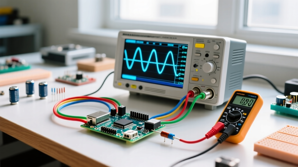
You cannot easily measure the inductance drop under load without a specialized bias current source attached to an LCR meter. However, you can measure the effect of saturation on your workbench using an oscilloscope. Probe the voltage across your current-sense resistor (or use a high-bandwidth current probe) on the switching node. If the current waveform shows a sharp, non-linear 'hook' or sudden steep spike at the peak of the switching cycle, your core is saturating due to excessive DC biased current.