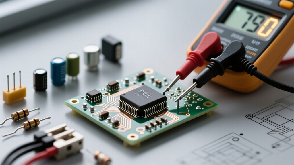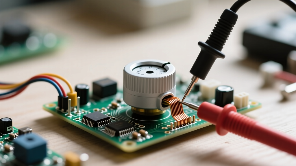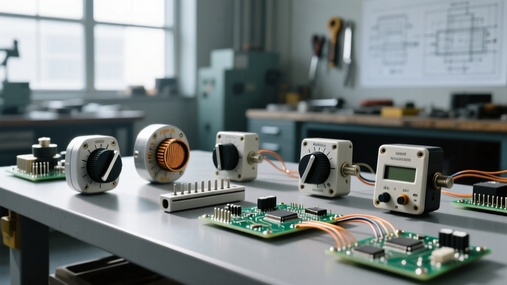

When designing analog interfaces, tuning feedback loops, or setting bias voltages, understanding the different types of potentiometer is critical. A potentiometer—colloquially known as a 'pot'—is fundamentally a three-terminal resistor with a sliding or rotating contact that forms an adjustable voltage divider. But not all pots are created equal. From the carbon-track rotary pots in guitar pedals to the silicon-based digital potentiometers in modern microcontrollers, the internal mechanics dictate their performance, lifespan, and ideal use case.
The Core Mechanism: The Voltage Divider Principle
Before categorizing the specific types of potentiometer, we must understand the underlying physics. A pot operates on the voltage divider principle. By applying a reference voltage across the two outer terminals (the resistive track), the wiper (the middle terminal) taps into a specific point along that track. According to Ohm's Law, the output voltage at the wiper is proportional to the ratio of the resistance between the wiper and ground versus the total resistance of the track.
For example, if you apply 5V across a 10kΩ potentiometer and position the wiper exactly at the mechanical center of a linear track, the resistance to ground is 5kΩ and the resistance to the 5V source is 5kΩ. The output voltage will be exactly 2.5V. This simple yet elegant mechanism allows for continuous analog control in a digital world.
Mechanical Form Factors: Rotary, Linear, and Presets
The most common way to classify these components is by their physical actuation method. The mechanical design directly impacts the user experience, mounting requirements, and resolution of the adjustment.
Single-Turn Rotary Potentiometers
These are the standard volume knobs found on amplifiers and the tuning dials on older radios. They typically offer a mechanical rotation of about 270 to 300 degrees. Inside, a wiper sweeps across a circular resistive element, which can be made of carbon composition, cermet, or conductive plastic. Carbon track pots are inexpensive (often under $0.50) but suffer from higher thermal noise and shorter lifespans. Conductive plastic elements, while more expensive, offer virtually infinite resolution and lifespans exceeding 1,000,000 cycles.
Multi-Turn Precision Pots
When extreme precision is required, such as in medical equipment calibration or laboratory power supplies, single-turn pots lack the necessary resolution. Multi-turn potentiometers, like the industry-standard Bourns 3590 series, use a worm-gear mechanism to move the wiper along a linear helical track. A 10-turn pot requires ten full 360-degree rotations to sweep from zero to maximum resistance. These are often wirewound (using nichrome or similar resistance wire) and cost significantly more, typically ranging from $10 to $25 per unit, but they provide unparalleled tuning accuracy.
Linear Slide Potentiometers (Faders)
Ubiquitous in audio mixing consoles and lighting control boards, slide pots move the wiper along a straight track. The primary advantage of a slide pot, such as the premium Alps RK27 series, is visual feedback. An engineer can instantly see the relative position of twenty different faders at a glance, something impossible with rotary knobs. However, their open mechanical design makes them highly susceptible to dust and debris ingress, which can cause 'scratchy' audio artifacts.
Trimpots (Preset Potentiometers)
Trimpots are designed for 'set-and-forget' applications. They are mounted directly to the PCB and adjusted with a small screwdriver during manufacturing or servicing. The Bourns 3296W is a classic multi-turn trimpot used for calibrating sensor offsets or setting operational amplifier gain limits.
Electrical Tapers: How Resistance Maps to Movement
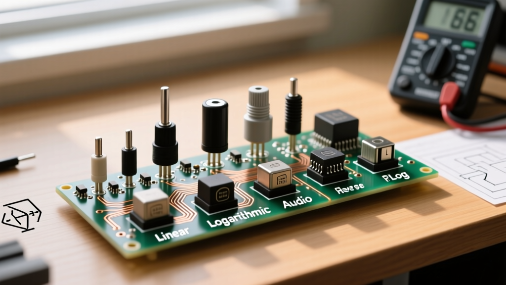
Beyond physical shape, types of potentiometer are also defined by their 'taper'—the mathematical relationship between the physical position of the wiper and the resistance ratio. Selecting the wrong taper will result in highly non-intuitive user controls.
| Taper Type | Industry Code | Resistance at 50% Rotation | Primary Application |
|---|---|---|---|
| Linear | B (or Lin) | 50% of Total | Position sensors, voltage dividers, oscillator tuning |
| Logarithmic (Audio) | A (or Log) | ~10% to 15% of Total | Audio volume controls (matches human hearing perception) |
| Reverse Logarithmic | C (or RevLog) | ~85% to 90% of Total | Specific tone controls, right-channel audio balancing |
| Anti-Log (S-Curve) | W or Custom | 50% (but non-linear curve) | Specialized lighting dimmers and motor speed controls |
Human hearing perceives loudness logarithmically. If you use a linear potentiometer for a volume knob, 80% of the perceived volume change will happen in the first 20% of the knob's rotation, making fine adjustments at high volumes nearly impossible. An Audio Taper (Log) pot compensates for this by increasing resistance slowly at first, then exponentially, resulting in a smooth, linear perceived volume increase.
Solid-State Alternatives: How Digital Potentiometers Work
While mechanical pots are excellent for human interfaces, they are terrible for automated, microcontroller-driven systems. Enter the digital potentiometer. Devices like the Microchip MCP4131 replace the physical resistive track and wiper with a series of discrete resistors and CMOS switches, often arranged in an R-2R ladder or a string DAC (Digital-to-Analog Converter) topology.
A typical 8-bit digital pot contains 256 individual resistor segments. A digital wiper, controlled via SPI or I2C protocols, connects the output to the desired node. Because there are no moving parts, digital pots are immune to mechanical wear, vibration, and dust. Furthermore, they allow a microcontroller to store 'presets' in non-volatile memory (EEPROM), meaning the device can remember its exact resistance state after a power cycle. However, they come with limitations: they are restricted to the voltage rails of the controlling IC (usually 3.3V or 5V), have limited bandwidth, and introduce slight step-noise when the wiper changes positions.
Real-World Failure Modes and Troubleshooting
Mechanical potentiometers are often the first component to fail in an electronic device. Understanding these failure modes is crucial for troubleshooting and designing robust circuits.
- Track Wear and Carbon Dust: Over time, the friction of the wiper wears down the carbon or cermet track. This creates microscopic debris that gets trapped between the wiper and the track, causing intermittent contact. In audio circuits, this manifests as a 'crackling' or 'scratchy' noise when the knob is turned. While contact cleaners (like DeoxIT) can temporarily wash away debris, the physical wear is permanent.
- Wiper Bounce: When a mechanical wiper moves rapidly across a track, it can physically bounce off the surface for a few milliseconds. In precision analog-to-digital conversion circuits, a 2ms wiper bounce can cause the microcontroller to read a massive, erroneous voltage spike. Hardware debouncing capacitors or software averaging filters are required to mitigate this.
- Thermal Noise (Johnson-Nyquist Noise): Carbon composition pots generate significantly more thermal noise than wirewound or metal film resistors. In high-gain preamplifier circuits, using a cheap carbon pot in the feedback loop will introduce a noticeable hiss into the signal chain.
Expert Insight: Never wire a potentiometer as a variable resistor (rheostat) without a fixed series resistor. If the wiper reaches the zero-ohm end of the track, it will effectively short your power supply to ground, potentially destroying the wiper trace, the power supply, or both. Always place a fixed resistor in series to limit the maximum current.
Selecting the Right Component for Your Design
Choosing between the various types of potentiometer depends entirely on the application's demands. If you are building a user-facing audio mixer, invest in high-cycle conductive plastic rotary pots or premium linear faders with an audio taper. If you are designing an automated gain-control circuit for an IoT sensor node, abandon mechanical parts entirely and utilize an I2C digital potentiometer. By matching the internal mechanics and taper profile to your specific electrical and environmental constraints, you ensure both the longevity and the precision of your circuit design.
For deeper technical specifications on mechanical tolerances and wiper contact resistance, refer to the Bourns Potentiometer Technical Guides. Additionally, the foundational theory of voltage dividers and variable resistance is thoroughly documented in the All About Circuits DC Electronics textbook. For modern solid-state implementations, Microchip's Digital Potentiometer Application Notes provide excellent schematics for integrating digital pots with modern microcontrollers.