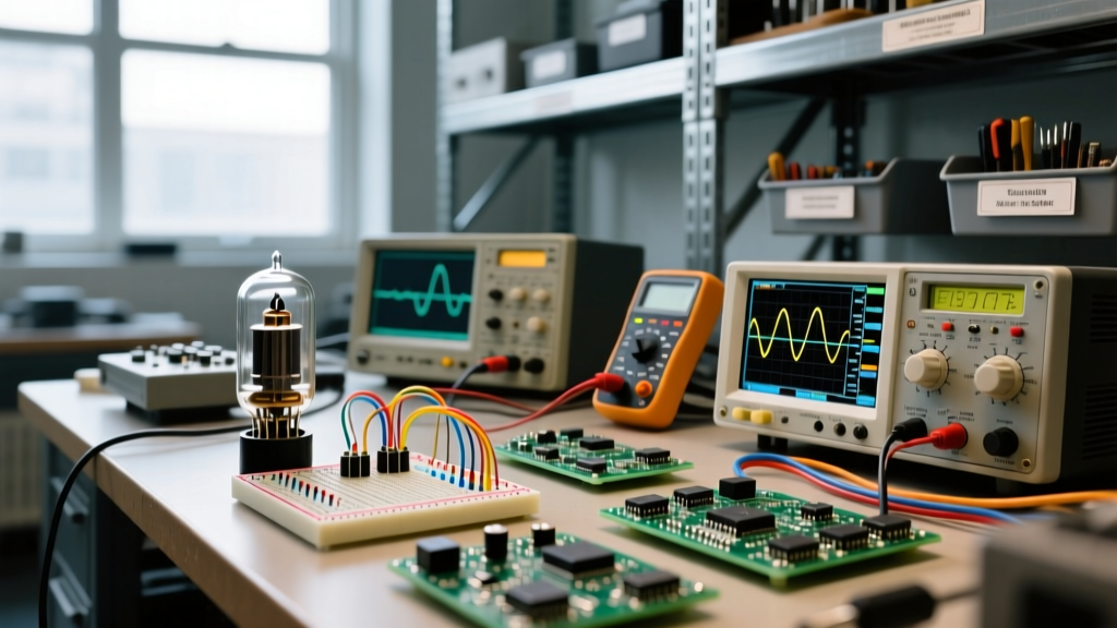

Tube electronics relies on vacuum-sealed glass or metal envelopes where thermionic emission releases electrons from a heated cathode, allowing a control grid's voltage to dictate current flow across a vacuum gap. In a real circuit, swapping solid-state for tubes fundamentally changes your impedance matching, demands high-voltage DC power supplies (often 200V to 500V+), and introduces significant thermal management requirements. Beginners commonly confuse the low-voltage AC/DC heater (filament) circuit with the high-voltage DC anode (plate) circuit, or mistakenly treat a tube like a current-controlled bipolar junction transistor (BJT) rather than a high-impedance voltage-controlled device.
The Core Physics: Thermionic Emission and the Vacuum Gap
At the heart of tube electronics theory is the triode, which consists of three primary elements inside an evacuated glass envelope. The cathode is typically a nickel tube coated in barium and strontium oxides. When the internal heater raises the cathode temperature to roughly 800°C, electrons gain enough thermal energy to escape the metal surface, forming a localized cloud known as the 'space charge'.
Surrounding the cathode is the control grid, a fine wire mesh. Because it sits between the cathode and the anode, applying a negative voltage to the grid repels the negatively charged electrons in the space charge, acting as a valve. Finally, the anode (plate) is held at a high positive DC potential, which aggressively pulls electrons through the grid mesh. The physical distance and the vacuum ensure that current flows in only one direction, giving the tube its inherent rectifying and amplifying properties.
Heater (Filament): 6.3V AC or DC | Control Grid Bias: -1.5V DC | Plate (Anode): +250V DC
Worked Numeric Example: Biasing a 12AX7 Preamp Stage
Let's design a common-cathode voltage gain stage using a 12AX7 (ECC83) dual triode, the most ubiquitous preamp tube in audio. Our goal is to set the DC operating point (bias) so the tube can amplify an AC audio signal with maximum symmetrical swing before clipping.
- Define the Supply and Target Plate Voltage: We have a regulated B+ supply of 250V. For maximum symmetrical swing, we want the quiescent plate voltage ($V_p$) to sit at roughly half the supply. Target $V_p = 125V$.
- Select Quiescent Plate Current ($I_p$): Consulting the 12AX7 datasheet, a plate current of 1.2mA provides a low-noise, highly linear operating point.
- Calculate the Plate Load Resistor ($R_p$): The resistor must drop the remaining 125V (250V supply - 125V plate) at 1.2mA. Using Ohm's Law: $R = V / I = 125 / 0.0012 = 104,166\Omega$. We select the nearest standard value: 100kΩ.
- Calculate the Cathode Bias Resistor ($R_k$): To make the grid negative relative to the cathode without a separate negative power supply, we raise the cathode voltage. For 1.2mA, the required grid bias ($V_g$) is approximately -1.5V. Therefore, the cathode must sit at +1.5V above ground. $R_k = 1.5V / 0.0012A = 1,250\Omega$. We select a standard 1.2kΩ or 1.5kΩ resistor. Using 1.5kΩ yields a slightly cooler bias of 1.8V, which extends tube life.
Where You Meet Tube Electronics in Practice
While silicon dominates modern computing, tube electronics remains critical in specific high-power and high-fidelity niches where solid-state devices struggle or fail entirely.
- Guitar and Hi-Fi Audio Amplifiers: The soft-clipping characteristics and high output impedance of tubes interact musically with loudspeaker voice coils and guitar pickups. Brands like McIntosh and Fender still rely heavily on output transformers to match the high-impedance tube plate to low-impedance speakers.
- High-Power RF Transmission: Ham radio linear amplifiers and commercial broadcast transmitters use massive tubes like the 3-500Z or 813. These tubes can easily dissipate kilowatts of heat and handle massive voltage swings that would instantly destroy LDMOS or GaN transistors.
- Microwave Ovens: The cavity magnetron hidden inside your kitchen microwave is technically a vacuum tube. It uses a heated cathode and a strong permanent magnetic field to force electrons into a circular path, generating 2.45 GHz RF energy to heat water molecules.
Real-World Scenario Walkthrough: The Missing Grid-Leak Resistor
Theory is clean; the workbench is messy. Here is a classic tube electronics failure that catches many first-time amp builders off guard.
The Setup: You are wiring a 12AX7 preamp stage on a point-to-point turret board. You successfully install the 100kΩ plate resistor, the 1.5kΩ cathode resistor, the 0.1µF coupling capacitor, and the 6.3V heater wiring. However, you forget to install the 1MΩ grid-leak resistor that ties the control grid to ground.
The Numbers: B+ is 250V. Heater is 6.3V AC. The control grid is connected to the input jack but has no DC path to ground (infinite impedance).
The Outcome: You power up the amplifier. For the first 30 seconds, it plays beautifully. Then, the audio severely distorts, the 12AX7 plate current spikes from the designed 1.2mA to over 8mA, and the internal plate structure begins to glow cherry red.
What Went Wrong: Inside the vacuum, stray electrons and residual gas ions inevitably strike the control grid. With a 1MΩ grid-leak resistor present, these accumulated charges bleed safely to ground. Without it, the grid accumulates a positive charge. This positive charge attracts a massive flood of electrons from the cathode, driving the tube into uncontrolled conduction (thermal runaway). The tube attempts to dissipate far beyond its 1.2W maximum plate rating, literally cooking itself from the inside out.
Common Confusions and Bench Mistakes
When transitioning from solid-state to modern vacuum tube design, hobbyists frequently make a few critical errors:
- Confusing Current-Control with Voltage-Control: A BJT transistor is a current-controlled device (base current dictates collector current). A tube is a voltage-controlled device, much like a MOSFET. The grid draws virtually zero DC current; it is the electrostatic field (voltage) that controls the plate current.
- Ignoring the Output Transformer: Solid-state amps can drive an 8-ohm speaker directly from the output devices. Tubes operate at high voltage and low current (high impedance). You cannot connect a tube plate directly to a speaker; the impedance mismatch would result in almost zero power transfer and likely destroy the tube. An iron-core output transformer is mandatory to step down the impedance.
- Microphonics vs. 60Hz Hum: If your tube amp howls when you tap the chassis, that is microphonics (mechanical vibration translating to electrical noise via the tube's internal elements). If it produces a steady low-frequency buzz, that is 60Hz/120Hz hum, usually caused by poor heater wiring routing, inadequate filter capacitance, or a ground loop.
FAQ: Tube Electronics on the Workbench
Can I directly swap a 12AX7 for a 12AT7 in my preamp?
Electrically, they share the same 9-pin pinout, but their internal characteristics are vastly different. The 12AT7 has a much lower amplification factor (mu of 60 vs the 12AX7's 100) and requires significantly more plate current. Dropping a 12AT7 into a circuit biased for a 12AX7 will result in a massive voltage drop across the plate resistor, pulling the plate voltage down to near zero and severely choking the signal. Always recalculate your bias resistors when changing tube types.
Why do tube amplifiers need a warm-up time?
The cathode coating requires time to reach the ~800°C threshold for efficient thermionic emission. If you apply high voltage to the plate before the cathode is fully heated, the tube will attempt to draw current from a cold, poorly emitting surface. This causes 'cathode stripping,' where the high electric field physically tears the emissive coating off the cathode, permanently degrading the tube's lifespan and increasing noise.
What exactly is 'red-plating' and can the tube recover?
Red-plating occurs when the plate dissipates more power than its thermal limits allow, causing the metal anode to glow red-hot from resistive heating. While a brief, accidental red-plate event might not instantly kill the tube, it often warps the internal grid structure and releases trapped gases from the metal, ruining the vacuum. Once a tube has red-plated severely, it should be considered compromised and replaced.