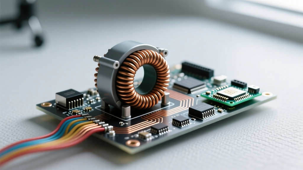

In physics, a transformer is a passive electrical device that transfers electrical energy between two or more circuits through electromagnetic induction, primarily to increase or decrease alternating voltage levels. It does not generate electrical power; instead, it changes the voltage-to-current ratio in a real circuit or installation while keeping the total transferred power (minus minor thermal losses) constant. Because it relies entirely on a changing magnetic field to operate, it is strictly an alternating current (AC) component. People commonly confuse standalone transformers with complete DC power supplies or 'wall wart' adapters, but a transformer only scales AC voltage—it does not rectify, filter, or regulate DC output.
The Core Physics: Electromagnetic Induction
The operation of a transformer is governed by Faraday’s Law of Induction and the principle of mutual inductance. When an alternating current flows through the primary winding, it generates a continuously expanding and collapsing magnetic field. This magnetic flux is channeled through a high-permeability core—typically made of silicon steel laminations to minimize eddy current losses—and intersects the secondary winding.
As the magnetic flux lines cut across the turns of the secondary coil, they induce an electromotive force (EMF), or voltage. The magnitude of this induced voltage is directly proportional to the ratio of turns between the two coils. The fundamental physics equation governing this relationship is:
Vp / Vs = Np / Ns = Is / Ip
Where V is voltage, N is the number of wire turns, I is current, and the subscripts p and s denote primary and secondary sides, respectively. In an ideal, lossless transformer, the power input equals the power output (Vp × Ip = Vs × Is).
Worked Numeric Example: Sizing a Control Circuit Transformer
To see how these physics principles translate to the workbench, let’s size a control transformer for an industrial motor starter panel. We need to step down a 480V AC mains supply to a safe 120V AC to power the contactor coils and indicator lights.
| Parameter | Symbol | Value |
|---|---|---|
| Primary Voltage | Vp | 480V AC |
| Secondary Voltage | Vs | 120V AC |
| Total Secondary Load | Is | 2.5 Amps |
| Turns Ratio | Np:Ns | 4:1 |
Step 1: Calculate the Primary Current
Using the inverse relationship between voltage and current, we calculate the primary current draw:
Ip = Is × (Vs / Vp)
Ip = 2.5A × (120V / 480V) = 0.625 Amps.
This tells us the 480V feeder only needs to supply 0.625A, allowing us to use smaller gauge wire and a lower-rated breaker on the primary side.
Step 2: Calculate the Required VA Rating
Transformer capacity is rated in Volt-Amps (VA), not Watts, to account for reactive loads like contactor coils.
Apparent Power = Vs × Is = 120V × 2.5A = 300 VA.
According to standard electrical engineering practices outlined in resources like the All About Circuits AC textbook, you must add a 20% to 25% safety margin for inrush currents when magnetic coils energize.
300 VA × 1.25 = 375 VA.
Step 3: Select the Standard Component
Transformers are manufactured in standard increments (50, 100, 150, 250, 500 VA). Since 375 VA exceeds the 250 VA standard size, you must select a 500 VA control transformer to ensure reliable operation without core saturation or thermal runaway.
Where You Meet Transformers in Practice
While the physics remains identical, the physical form factor of a transformer changes drastically based on its application:
- Distribution 'Pole Pigs': The cylindrical tanks on utility poles are massive step-down transformers. They take 7,200V from the primary distribution line and step it down to 240V/120V split-phase for residential service, utilizing oil for both insulation and cooling.
- Current Transformers (CTs): Used in metering and protective relaying, CTs step down high currents to measurable levels. A 200:5 CT will output exactly 5A on its secondary when 200A flows through the primary conductor, allowing standard panel meters to read massive industrial loads safely.
- Audio Isolation Transformers: In professional audio, 1:1 transformers are used to pass AC audio signals while blocking DC and breaking ground loops, eliminating 60Hz mains hum without degrading signal fidelity.
- Switch-Mode Power Supply (SMPS) Ferrites: Inside your laptop charger, high-frequency ferrite core transformers operate at 50kHz to 100kHz. Because Faraday's law dictates that higher frequencies induce more voltage per turn, these transformers can be incredibly small compared to 60Hz iron-core equivalents.
Common Confusions: Transformers vs. Power Supplies
The most frequent mistake hobbyists make is assuming a transformer outputs DC or regulates voltage. A transformer is strictly a magnetic scaling device. If you measure the output of a raw transformer with a multimeter, you will read AC voltage that fluctuates directly with the mains input. If the grid voltage sags by 10%, the transformer's secondary voltage sags by exactly 10%.
To get a stable DC output, the transformer must be followed by a rectifier (diodes to convert AC to pulsing DC), a filter (capacitors to smooth the ripple), and a regulator (linear or switching ICs to hold the voltage steady). When you buy a 'power supply,' you are buying this entire chain; when you buy a 'transformer,' you are only buying the first magnetic stage. For a deeper dive into how these stages integrate, the Electronics Tutorials transformer guide provides excellent schematics showing the transition from raw AC induction to smoothed DC.
Frequently Asked Questions
Can a transformer change DC voltage?
No. A transformer requires a changing magnetic field to induce voltage in the secondary coil, which only alternating current (AC) can provide. To step up or step down DC voltage, you must use an active electronic circuit like a buck, boost, or buck-boost DC-DC converter, which uses high-frequency switching and inductors to achieve the transformation.
Why do large transformers hum or vibrate?
The hum is caused by a physical phenomenon called magnetostriction. As the alternating magnetic flux passes through the steel core laminations, the metal physically expands and contracts microscopically. In a 60Hz AC system, this expansion happens twice per cycle, resulting in a fundamental vibration frequency of 120Hz, which manifests as an audible low-pitch hum.
What happens if you wire a step-down transformer backward?
Electrically, the physics of mutual inductance work in reverse, so a 480V-to-120V transformer will step 120V up to 480V if fed backward. However, this is highly dangerous in practice. The original secondary winding (now acting as the primary) is wound with thinner wire designed for higher current. If you use it on a high-voltage source, the insulation may fail, and the wire gauge is not rated for the magnetizing current required, leading to rapid overheating.
Does a transformer consume power when nothing is plugged into the secondary?
Yes. This is known as 'no-load loss' or 'core loss.' Even with an open secondary circuit, the primary winding draws a small magnetizing current to maintain the magnetic field in the core. Energy is lost to hysteresis (the friction of realigning magnetic domains in the steel) and eddy currents (stray circulating currents in the core). In modern distribution transformers, these losses typically account for 0.5% to 2% of the unit's total rated capacity.


