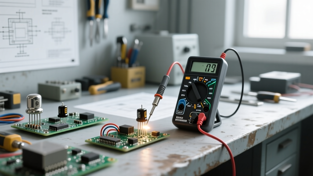
To accurately test a capacitor, you must first safely discharge it, remove it from the circuit (or lift one leg to isolate it from parallel paths), and measure it using a multimeter with a dedicated capacitance setting or a dedicated ESR meter. A healthy capacitor will read within ±20% of its printed nominal value, and an aluminum electrolytic capacitor should show an Equivalent Series Resistance (ESR) well under 1 ohm—typically under 0.1 ohms for values above 100µF at 100kHz. If the capacitance reads significantly low, the ESR reads high, or the multimeter reads a dead short, the component has failed and must be replaced.
Never test a capacitor directly after removing power. Large electrolytics in power supplies and CRT circuits can hold lethal charges for days. Discharge them using a high-wattage bleed resistor (e.g., a 1kΩ to 10kΩ, 5W ceramic resistor) across the terminals for at least 10 seconds, then verify with a DC voltmeter that the reading is 0V. Never short large capacitors directly with a screwdriver; the instantaneous current spike can vaporize the metal, destroy the capacitor's internal foil, and blind you with shrapnel.
The Direct Answer: How to Test a Capacitor on the Bench
Testing a capacitor requires looking at two distinct parameters: capacitance (ability to store charge) and ESR (internal parasitic resistance). Standard multimeters only measure capacitance, which is why a capacitor can test 'good' on a cheap meter but still cause a circuit to fail due to high ESR.
Step-by-Step Testing Procedure
- Isolate: Desolder and remove the capacitor. In-circuit testing is notoriously unreliable because parallel components (especially resistors and semiconductors) will skew both capacitance and ESR readings.
- Set the Meter: Switch your multimeter to the capacitance setting (usually marked with an 'F' or 'µF'). If using an ESR meter, switch it to the 100kHz test frequency mode.
- Measure Capacitance: Connect the leads. For polarized electrolytics, red to the anode (+), black to the cathode (-). Wait for the reading to stabilize. A 470µF capacitor reading 410µF is acceptable (within the standard -10%/+50% tolerance for electrolytics). A reading of 120µF indicates severe electrolyte drying.
- Measure ESR: Connect your ESR meter. For a standard 1000µF, 16V aluminum electrolytic capacitor, a good ESR reading is < 0.08Ω. For a 'Low-ESR' variant (like those used in CPU VRMs), it should be < 0.02Ω. If your meter reads > 1.0Ω on a large power filter cap, it is effectively an open circuit at switching frequencies and must be scrapped.
Decoding Capacitor Markings and Codes
When testing the capacitor and sourcing a replacement, you must accurately read the physical markings. While large electrolytics print their values plainly (e.g., '1000µF 25V'), smaller ceramics and films rely on the EIA (Electronic Industries Alliance) 3-digit coding system.
The 3-Digit EIA Capacitance Code
The first two digits represent the significant figures, and the third digit is the multiplier (number of zeros to add), calculated in picofarads (pF).
- 104: 10 + 4 zeros = 100,000 pF = 100 nF = 0.1 µF
- 473: 47 + 3 zeros = 47,000 pF = 47 nF
- 221: 22 + 1 zero = 220 pF
- 339: 33 × 0.1 (the '9' multiplier means divide by 10) = 3.3 pF
Tolerance and Voltage Letter Codes
Following the numeric code, a single letter indicates tolerance. J = ±5%, K = ±10%, M = ±20%. If you are testing the capacitor in a precision timing circuit (like a 555 oscillator), a 'K' or 'M' tolerance part is unacceptable; you must source a 'J' or 'G' (±2%) replacement.
Surface-mount and small axial capacitors often use a letter-number combo for voltage ratings. Memorize these common EIA voltage prefixes:
- 1A: 10V | 1C: 16V | 1E: 25V
- 1H: 50V | 1J: 63V | 2A: 100V
- 2E: 250V | 2G: 400V | 2J: 630V
Capacitor Types: Construction, Tolerance, and Use Cases
Knowing which type of capacitor you are testing dictates how you interpret the failure. A shorted ceramic capacitor behaves entirely differently from a dried-out electrolytic. For a deeper dive into dielectric physics, refer to the Analog Devices guide on capacitor dielectrics.
| Type | Construction / Dielectric | Typical Tolerance | Tempco / Stability | Typical Use Case |
|---|---|---|---|---|
| Ceramic (MLCC) | Alternating layers of ceramic and metal | ±10% to -20%/+80% | C0G (Excellent), X7R (Good), Y5V (Poor) | High-frequency decoupling, RF bypass, snubbers |
| Aluminum Electrolytic | Etched aluminum foil with liquid/polymer electrolyte | -20% to +50% | Poor (High tempco, dries out over time) | Bulk power supply filtering, audio coupling, energy storage |
| Tantalum | Sintered tantalum powder with manganese dioxide cathode | ±10% to ±20% | Moderate (Stable over time, but temp sensitive) | Compact SMD power filtering, medical/aerospace hold-up |
| Film (Polypropylene) | Metalized plastic film wound or stacked | ±1% to ±5% | Excellent (Self-healing, highly linear) | High-voltage snubbers, audio crossovers, AC motor run |
Visual and Electrical Failure Modes
When testing the capacitor, visual inspection is just as critical as meter readings. Different chemistries fail in distinct, recognizable ways.
Aluminum Electrolytic: The 'Bulge and Leak'
The liquid electrolyte inside these capacitors slowly vaporizes over time, accelerated by heat and ripple current. As internal pressure builds, the rubber bung at the bottom may leak, leaving a crusty brown residue on the PCB, or the scored 'X' on the top dome will pop open. Electrical symptom: Massive capacitance drop (e.g., a 1000µF cap measuring 150µF) and ESR spiking above 2 ohms.
Ceramic (MLCC): The Invisible Short
Multilayer Ceramic Capacitors rarely show visual damage unless completely shattered. Their primary failure mode is flex cracking. If the PCB bends (during depanelization, connector insertion, or thermal shock), the brittle ceramic cracks internally, creating a short circuit between the interleaved plates. Electrical symptom: Multimeter reads 0.0 ohms (dead short). Capacitance mode will fail to register a value.
Tantalum: Thermal Runaway
Tantalum capacitors are notoriously unforgiving. If subjected to reverse polarity, voltage spikes exceeding their rating, or excessive ripple current, the manganese dioxide dielectric breaks down. Because tantalum is highly reactive, this results in catastrophic thermal runaway—the part will literally catch fire, emit acrid white smoke, and melt into a black lump. Substitution rule: Never substitute a standard aluminum electrolytic for a tantalum in high-frequency switching circuits without verifying ESR requirements; conversely, always replace a failed tantalum with a modern Polymer Tantalum (which is fire-safe) or a Low-ESR ceramic.
The Substitution Decision Tree: Picking the Right Replacement
When testing the capacitor reveals a dead part, you rarely have the exact OEM component in your bench bins. Use this decision path to substitute safely. For comprehensive hobbyist component data, the SparkFun Capacitor Tutorial remains an excellent baseline reference.
1. Voltage: You can always go UP in voltage rating (e.g., replacing a 25V cap with a 50V cap). Never go down.
2. Temperature: Always replace 85°C rated electrolytics with 105°C rated parts for power supplies.
3. Polarity: Never put a polarized capacitor in a non-polarized circuit (like an audio crossover or AC line). Use a non-polar electrolytic or back-to-back series wiring if forced.
| Application Context | Critical Parameter | Substitution Logic (If Exact Part Missing) | Default Concrete Pick (Buy This) |
|---|---|---|---|
| SMPS Output Filter (Buck/Boost Converters) | Ultra-Low ESR, High Ripple Current Rating | Must use 'Low-ESR' 105°C Al-Elec or Polymer. Standard electrolytics will overheat and fail in weeks. | Panasonic FM or FR Series (e.g., EEUFM1V101 for 100µF 35V) |
| Timing / Oscillator (555 Timers, Crystal Loads) | Tight Tolerance (±5% or better), Zero Tempco | Must use C0G/NP0 Ceramic or Polystyrene Film. Never use X7R or Y5V ceramics; their capacitance drops 50% under DC bias. | KEMET C0G/NP0 MLCC (e.g., C315C100J1G5TA for 10pF) |
| Audio Signal Coupling (Pre-amps, DAC Outputs) | Low Dielectric Absorption, Non-Polar, Low THD | Use Film capacitors. If space is tight, use bipolar (NP) electrolytics, but avoid standard polarized Al-Elecs. | WIMA MKS2 Film or Nichicon MUSE (BP) Series |
| Bulk Rectifier Filter (Linear PSU, 50/60Hz) | High Capacitance, High Voltage, Moderate ESR | Standard 105°C snap-in or radial electrolytics are fine. Higher µF than original is acceptable and often beneficial for reducing 120Hz ripple. | Nichicon LGG or Nippon Chemi-Con KMG snap-in series |
| High-Frequency Bypass (IC VCC pins, 0.1µF) | Low ESL (Equivalent Series Inductance) | Use the smallest physical SMD package that fits the pads (0402 or 0603). Smaller body = lower inductance. | TDK X7R 0603 0.1µF 25V (e.g., C1608X7R1H104K) |
By strictly following this testing methodology and substitution matrix, you eliminate the guesswork on the bench. When testing the capacitor yields a failed part, you now have the exact data to decode its markings, understand why it failed, and solder in a replacement that will outlast the original OEM component.