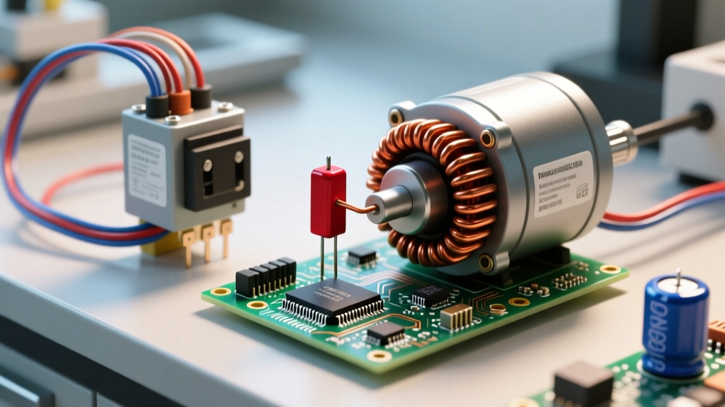
The direct answer: you cannot reliably measure exact capacitance (µF or nF) in-circuit with a standard digital multimeter (DMM). Parallel components on the PCB will skew the charge-time measurement, giving you wildly inflated readings or an 'OL' error. However, you can test a capacitor with a multimeter without removing it to check for catastrophic failures—specifically dead shorts and severe internal leakage—using the resistance (Ohms) setting. This guide covers the exact meter setup, probe placement, and numerical thresholds you need to identify a shorted or leaky capacitor while it remains soldered to the board, along with the safety categories required for mains-powered equipment.
The Hard Truth About In-Circuit Capacitor Testing
When a multimeter measures capacitance, it applies a small test voltage and times how long the component takes to charge. In a vacuum, this works perfectly. On a populated PCB, the capacitor is surrounded by parallel resistors, semiconductor junctions, and other capacitors. These parallel paths provide alternate routes for the test current, causing the DMM's internal microcontroller to miscalculate the charge curve.
If you put your meter in capacitance mode and probe an in-circuit 10µF electrolytic cap, you might see a reading of 45µF, or the meter might simply timeout and display 'OL'. This doesn't mean the capacitor is bad; it means the parallel circuit is interfering. Therefore, in-circuit testing with a standard DMM is strictly a fault-finding exercise for shorts and gross leakage, not a verification of capacitance value.
Meter Setup and Safety Categories
If you are working on boards connected to AC mains (like a switch-mode power supply input stage), your multimeter must be rated CAT II or CAT III per IEC 61010 standards to handle transient voltage spikes. A CAT III 600V meter (like the Fluke 87V or Brymen BM235) is the minimum safe choice for mains-adjacent diagnostics.
Meter Setup Block
- Dial Position: Resistance (Ω) / Ohms. If your meter is manual-ranging, start at the 200kΩ or 2MΩ range. Do not use the continuity/beep mode, as the rapid sampling can misinterpret the capacitor's initial inrush charge as a short.
- Lead Jacks: Black lead to COM, Red lead to the V/Ω jack.
- Discharge Tool: A 100Ω 5W power resistor with alligator clips (never use a flathead screwdriver to short the leads; the current spike can vaporize the trace or damage the capacitor's internal foil).
Step-by-Step: Testing for Shorts and Leakage In-Circuit
- De-energize and Verify: Unplug the device. Use your DMM in DC Voltage mode to verify that the voltage across the target capacitor's leads is 0V. If voltage is present, discharge it with your bleeder resistor and re-verify.
- Probe Placement: For polarized electrolytic capacitors, place the Red probe on the Anode (+) and the Black probe on the Cathode (-). For non-polarized ceramics or film capacitors, polarity does not matter. Ensure your probe tips are making solid contact with the solder joints or the exposed metal leads, not the conformal coating or flux residue.
- Observe the Charge Curve: Watch the DMM display immediately upon contact. A healthy capacitor will act like a temporary short as it charges from the meter's internal battery, then the resistance reading will climb rapidly as the voltage across the cap equalizes with the meter's test voltage.
- Hold and Read: Hold the probes steady for 10 to 15 seconds. Note the final stabilized resistance value. (If the reading continuously climbs and eventually hits 'OL' or >20MΩ, the capacitor's internal leakage is negligible).
Expected Readings: Good vs. Bad Capacitors (Resistance Mode)
The following table outlines what your multimeter should display when testing in-circuit. Note that parallel components (like a 10kΩ bleeder resistor intentionally placed across a power supply cap) will cap your maximum reading at 10kΩ. Always check the schematic for parallel paths if a reading seems suspiciously low.
| Capacitor Type | Good Reading (Healthy) | Bad Reading (Shorted) | Bad Reading (Leaky) |
|---|---|---|---|
| Electrolytic (10µF - 1000µF) | Starts low (1kΩ-10kΩ), climbs steadily to OL or >2MΩ | Stays pinned at 0Ω - 10Ω | Stabilizes below 50kΩ (assuming no parallel resistors) |
| Electrolytic (>1000µF) | Starts near 0Ω, climbs slowly over 10-30 seconds to OL | Stays pinned at 0Ω - 10Ω | Stabilizes below 20kΩ |
| Ceramic / Film (<1µF) | Instantly reads OL (charge time is faster than DMM sampling rate) | Stays pinned at 0Ω - 10Ω | Reads a stable value <500kΩ |
When In-Circuit Testing Fails: The ESR Alternative
If your DMM resistance test shows an open circuit (OL) but the device is still malfunctioning (e.g., an LCD monitor with a black screen or a motherboard that fails to POST), the capacitor likely suffers from high Equivalent Series Resistance (ESR). A standard multimeter cannot measure ESR. The internal electrolyte has dried out, turning the capacitor into a high-impedance bottleneck that blocks AC ripple current while still passing your DMM's DC resistance test.
To accurately test a capacitor with a multimeter without removing it for ESR and true capacitance, you need a dedicated ESR Meter. ESR meters inject a high-frequency AC signal (typically 100kHz). At this frequency, the capacitor's reactance drops to near zero, allowing the meter to measure only the parasitic series resistance. Crucially, parallel inductors and low-value resistors on the PCB do not skew this high-frequency measurement the way they ruin standard DMM capacitance tests.
Budget options like the MESR-100 (approx. $45) or professional tools like the Peak Atlas ESR70 (approx. $135) are mandatory for serious in-circuit PCB repair. According to DigiKey's technical guidelines on capacitor aging, an ESR reading above 5Ω on a high-frequency switching regulator capacitor is usually grounds for immediate replacement, regardless of what the capacitance value reads.
Frequently Asked Questions
Can I test a capacitor with a multimeter without removing it using the capacitance setting?
No, not reliably. The capacitance (µF/nF) setting on a standard DMM measures the DC charge time of the component. When left in-circuit, parallel resistors, transformer windings, and semiconductor junctions provide alternate paths for the test current. This will result in a reading that is drastically higher than the capacitor's actual value, or an 'OL' timeout error. You must desolder at least one leg of the capacitor to isolate it for an accurate capacitance measurement.
Why does my multimeter show low resistance when testing a capacitor without removing it?
A stable low-resistance reading (e.g., 4.7kΩ) on a healthy capacitor usually indicates a parallel circuit path, not a leaky capacitor. Power supply designers frequently place high-wattage bleeder resistors (often between 10kΩ and 100kΩ) across large primary smoothing capacitors to safely discharge them when the device is unplugged. Your multimeter is simply reading the parallel bleeder resistor. Consult the board schematic or look for a physically large resistor soldered adjacent to the capacitor to confirm.
Is it safe to test a capacitor with a multimeter without removing it from a mains-powered board?
You must never test components on a live, energized board. Always unplug the device, wait for the bulk capacitors to discharge, and verify 0V with your meter before switching to resistance mode. Furthermore, if you are probing the primary (high-voltage) side of a switch-mode power supply, your multimeter must carry a CAT II or CAT III safety rating to protect against transient voltage spikes that can arc across the PCB. For more on electrical safety boundaries, refer to Fluke's guide on multimeter safety ratings.
How do you test a ceramic capacitor with a multimeter without removing it?
Ceramic capacitors rarely suffer from the electrolyte drying out; when they fail, they almost always fail as a dead short due to mechanical cracking or dielectric breakdown. Set your DMM to the lowest Ohms range (e.g., 200Ω) and probe across the ceramic cap in-circuit. A good ceramic capacitor will instantly read 'OL' because its capacitance is too small to register a visible charge curve on a standard DMM. If the meter reads between 0Ω and 20Ω, the capacitor is shorted and must be replaced. Note that a shorted semiconductor (like a parallel diode or transistor) can mimic a shorted ceramic cap, so if the reading is ambiguous, you must lift one leg to isolate the fault.