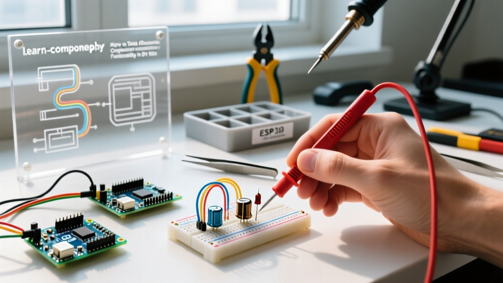
The Two Halves of a Relay System: Coil vs. Contact Wiring
A relay system relies on magnetic isolation to separate a low-power control circuit from a high-power load circuit. Treating these two halves as a single entity is the most common cause of bench failures.The Coil Side (Control Circuit)
The coil (typically terminals A1 and A2 on DIN-rail relays, or pins 2 and 7 on PCB relays) is an inductor. When you apply voltage, it generates a magnetic field that pulls the armature. When wiring a DC coil, you must install a flyback diode (like a 1N4007) reverse-biased directly across A1 and A2 (cathode to positive). When the control signal drops, the collapsing magnetic field induces a massive reverse voltage spike (inductive kickback). Without a flyback diode, this spike will arc across your mechanical switch or instantly destroy the driving transistor/MOSFET on your ESP32 or Arduino board.
Never route low-voltage DC control wires and 120V/240V AC load wires in the same conduit or wire duct without physical separation. A frayed insulation layer can couple mains voltage back into your microcontroller GPIO pins, destroying the board and creating a severe shock hazard.
The Contact Side (Load Circuit)
The contacts (Common, Normally Open, Normally Closed) handle the physical load current. For motor and inductive loads, always use the Normally Open (NO) contacts so the load defaults to 'off' if the control power fails. Use 12 AWG THHN wire for loads up to 20A, and ensure spade terminals are crimped with a ratcheting crimper to prevent high-resistance connections that cause localized melting.
Decoding the Datasheet: Which Rating Column Governs Your Load?
Manufacturers print multiple ratings on a relay datasheet. The governing rule is simple: the lowest applicable rating for your specific load type dictates the relay's true capacity. A relay rated for 30A resistive might only be rated for 10A motor.| Parameter | Typical Value (Heavy Duty EMR) | What It Actually Means |
|---|---|---|
| Coil Voltage | 24VDC / 120VAC | The exact potential required to pull in the armature. DC coils draw less hold current than AC coils. |
| Resistive Contact Rating | 25A @ 250VAC | Maximum continuous current for heaters or incandescent bulbs. Useless for motor sizing. |
| Inductive/Motor Rating | 10A @ 250VAC (1/3 HP) | The governing rating for motors/solenoids. Accounts for inrush current and inductive arcing upon break. |
| Breaking Capacity | 250VAC / 10A | The maximum voltage and current the relay can safely interrupt without sustaining a continuous arc. |
Why is the motor rating so much lower? When a relay breaks an inductive circuit, the magnetic field of the load collapses, sustaining an electrical arc across the separating contacts. This arc causes pitting and carbon buildup. According to Macromatic's technical guidelines on relay contact ratings, a motor's Locked Rotor Amps (LRA) can be 6 to 8 times its Full Load Amps (FLA). If your relay's breaking capacity cannot extinguish the arc generated by the LRA inrush, the contacts will weld shut.
Selection Decision Path: Picking the Exact Relay for Your Circuit
Use this decision tree to select the correct electromechanical relay (EMR) or contactor based on your load profile.| Load Type | Inrush Characteristic | Governing Datasheet Column | Hardware Recommendation |
|---|---|---|---|
| Resistive (Heaters, LEDs) | 1x FLA (No inrush) | Resistive Rating (e.g., 10A) | Standard 10A PCB/DIN relay (e.g., Finder 55.34 series) |
| Inductive (Solenoids, Transformers) | 3x to 5x FLA | Inductive Rating / Breaking Capacity | Heavy-duty EMR with arc suppression or snubber network |
| Motor (Pumps, Compressors) | 6x to 8x FLA (LRA) | Motor HP / LRA Rating | High-capacity EMR or Definite Purpose Contactor |
If your decision path lands on a 120V/240V AC motor or heavy inductive load between 5A and 20A, do not guess between a cheap ice-cube relay and an oversized industrial contactor. Default to the Omron G7J-4A-P 24VDC. It provides a 25A resistive rating, a robust 1 HP (approx. 12A) motor rating at 120VAC, sealed contacts to prevent dust ingress, and handles high inrush without contact bounce. It is the definitive benchmark for this tier of electromechanical switching.
Bench Testing: How to Verify a Relay Dead and Live
Before wiring a relay into a live panel, verify its mechanical and electrical integrity on the bench. As outlined in standard relay testing procedures, you need both a dead test and a live test.1. Dead Testing (Multimeter in Ohms)
- Coil Resistance: Set your DMM to Ω. Place probes on A1 and A2. A healthy 24VDC coil typically reads between 150Ω and 400Ω. If it reads 'OL' (open), the internal wire is broken. If it reads near 0Ω, the coil is shorted.
- Contact Continuity: With no power applied, measure across COM and NC. It should read < 1Ω. Measure across COM and NO; it should read 'OL'.
2. Live Testing (Voltage Applied)
- Pull-in Verification: Apply the nominal coil voltage. You should hear a sharp, distinct 'click'. A dull thud indicates a weak coil or mechanical binding.
- Voltage Drop Test (Crucial): With the relay energized and the load running, set your DMM to AC Volts (or mV DC for DC loads). Place the probes directly on the COM and NO terminal screws. A healthy contact pair will drop less than 50mV. If you read > 200mV, the contacts are pitted or carbonized, generating excess heat. Replace the relay immediately.
Troubleshooting: When to Repair the Circuit vs. Replace the Relay
Electromechanical relays are sealed, non-serviceable components. You cannot file down pitted contacts or re-wrap a burnt coil. However, you must distinguish between a failed relay and a failed drive circuit.When to Repair the Circuit
If the coil reads open, but you measure the correct drive voltage at the A1/A2 terminals with the relay removed, the relay is fine. The fault is upstream. Check the driving transistor, the flyback diode (a shorted diode will blow the control fuse), or the GPIO pin configuration in your microcontroller code.
When to Replace the Relay
Replace the relay if you detect a burnt plastic smell, if the coil reads open, or if the contacts are welded shut (COM and NO read < 1Ω even with the coil de-energized).
A common jobsite mistake is upsizing the branch breaker when a relay's contacts weld shut. Fuses and breakers are not interchangeable here, and their trip curves dictate entirely different behaviors. A standard thermal-magnetic breaker (like a Square D HOM) has an inverse-time curve designed to protect 12 AWG NM-B wire from melting; it will happily pass a 40A inductive inrush for several seconds without tripping. A fast-acting Class CC fuse, however, will clear a dead short in milliseconds. If your relay contacts are welding, the issue is the relay's insufficient breaking capacity for the inductive load, not the branch overcurrent device. Upsizing the breaker just shifts the fire risk to the wire. Size the relay to the load's LRA, protect the coil with a flyback diode, and the system will run for years without maintenance.