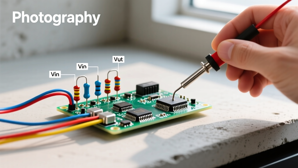

A simple resistor circuit relies on series resistance to drop voltage or limit current without active regulation. The direct answer to "how do I drop a voltage safely with just resistors" is to use a voltage divider topology, selecting E24 standard resistor values that satisfy both your target voltage and your load's current draw. For a standard 5V to 3.3V logic level shift, a 1.8kΩ and 3.3kΩ resistor pair will yield a safe 3.23V output while drawing less than 1mA of quiescent current.
The Anatomy of a Simple Resistor Circuit
Before picking components, we must define the physical topology. The most common configuration for signal conditioning is the unloaded voltage divider. This circuit consists of two resistors in series connected across a voltage source.
Node Labels and Topology:
- Node Vin: The input voltage source (e.g., 5.0V from a USB bus).
- Node A (The Junction): The electrical connection point between Resistor 1 (R1) and Resistor 2 (R2). This is where the divided voltage is tapped.
- Node Vout: The output terminal connected to Node A, feeding the load (e.g., a microcontroller ADC pin).
- Node GND: The common ground reference (0V) connected to the bottom of R2 and the negative terminal of the Vin source.
Current flows from Node Vin, through R1, into Node A, and then splits: a tiny fraction enters the load at Node Vout, while the vast majority continues through R2 to Node GND. According to Kirchhoff's Voltage Law, the sum of the voltage drops across R1 and R2 must exactly equal Vin.
Design Walkthrough: 5V to 3.3V Logic Level Shifter
Let’s design a simple resistor circuit to safely read a 5V digital signal with an ESP32-WROOM-32, which has a strict 3.6V absolute maximum rating on its GPIO pins. We want a nominal Vout of ~3.3V.
1. The Math:
The voltage divider formula is: Vout = Vin * (R2 / (R1 + R2))
2. Picking Real Component Values:
We need to choose from the standard E24 resistor series (5% tolerance). Let’s anchor R2 to 3.3kΩ.
Rearranging the formula to solve for R1: R1 = R2 * ((Vin / Vout) - 1)
R1 = 3300 * ((5.0 / 3.3) - 1) = 3300 * 0.515 = 1699Ω
The closest standard E24 value is 1.8kΩ. Let’s verify the actual output with these real-world components:
Vout = 5.0 * (3300 / (1800 + 3300)) = 5.0 * (3300 / 5100) = 3.235V
This 3.23V output is perfectly safe for the ESP32 (well under the 3.6V limit) and registers as a solid logic HIGH.
3. Power and Wattage Sizing:
Total series resistance is 5.1kΩ. The continuous bleed current is I = 5.0V / 5100Ω = 0.98mA.
Power dissipated by R1: P = I² * R = (0.00098)² * 1800 = 1.7mW.
Standard 1/4W (250mW) through-hole carbon film resistors (like the Yageo CFR-25 series) are vastly overrated for this, which is exactly what we want for reliability.
Behavior and Failure Mode Matrix
Understanding what breaks at the extremes is what separates a hobbyist from an engineer. In a simple series resistor topology, a single component failure radically alters the circuit's behavior. Here is the failure-mode contrast for our 5V to 3.3V divider:
| Fault Condition | Vout Result | Circuit Behavior | Risk to 3.3V Load |
|---|---|---|---|
| R1 Opens (broken trace/burnt resistor) | 0.0V | Current path to Vin is broken. Node A is pulled to GND via R2. | Safe. Microcontroller reads logic LOW. |
| R1 Shorts (solder bridge) | 5.0V | Vin connects directly to Node A. R2 is bypassed. | CRITICAL. 5V hits the 3.3V GPIO. Likely destroys the ESP32 silicon. |
| R2 Opens (broken trace/burnt resistor) | 5.0V (Unloaded) | Path to GND is broken. Node A floats up to Vin through R1. | CRITICAL. If load impedance is high, 5V reaches the GPIO pin. |
| R2 Shorts (solder bridge) | 0.0V | Node A is hard-tied to GND. R1 sees full 5V across it. | Safe. GPIO reads LOW. R1 dissipates 13.8mW (well within 1/4W rating). |
Notice the asymmetry: failures that remove the top resistor (R1) or the bottom resistor (R2) from the circuit both result in a fail-deadly condition (5V at the output) if the load is high-impedance. This is why critical industrial sensors often use active clamping diodes alongside simple resistor circuits.
Why Choose a Passive Resistor Topology Over Active Alternatives?
Why use a simple resistor circuit when you could use an LDO voltage regulator or a Zener diode? The decision comes down to current requirements, cost, and board space.
- Voltage Divider (Passive Resistors): Wins for high-impedance signal translation (like ADC inputs or logic level shifting). It costs fractions of a cent, requires no decoupling capacitors, and introduces zero switching noise. Choose this when the load draws less than 1mA and the input impedance is >100kΩ.
- LDO Regulator (e.g., AMS1117-3.3): Wins for powering loads. An LDO maintains 3.3V whether the load draws 1mA or 500mA. A resistor divider's output voltage will collapse under a 500mA load. Choose this when powering a microcontroller or sensor suite.
- Zener Diode + Series Resistor: Wins for crude overvoltage clamping. A 3.3V Zener diode placed in parallel with R2 will hard-clamp the voltage at 3.3V even if R1 shorts. However, Zeners have a soft "knee" and leak current below their rated voltage, making them poor choices for precision ADC scaling.
Step-by-Step Breadboard Testing Procedure
Never trust a theoretical calculation without bench verification. Follow this exact sequence to test your simple resistor circuit on a solderless breadboard using a digital multimeter (DMM).
- Visual and Continuity Check (Power OFF): Insert the 1.8kΩ (brown-grey-red-gold) and 3.3kΩ (orange-orange-red-gold) resistors. Set your DMM to continuity mode. Probe Node Vin to Node GND. It should not beep (you should read ~5.1kΩ in resistance mode, not a dead short).
- Verify Source Voltage: Power the breadboard. Set DMM to DC Volts. Probe Node Vin to Node GND. Confirm it reads between 4.8V and 5.2V. If it reads 4.2V, your USB port is sagging, and your Vout math will be wrong.
- Measure Unloaded Vout: Probe Node A (Vout) to Node GND. You should read exactly 3.23V (±5% for resistor tolerance, so 3.06V to 3.40V is acceptable).
- Load Regulation Test: Connect a 10kΩ pull-down resistor between Node Vout and GND to simulate a microcontroller's internal impedance. Measure Vout again. It will drop slightly (to ~3.18V) because the 10kΩ load is now in parallel with the 3.3kΩ R2. This confirms your Thevenin equivalent resistance is low enough to drive the load.
Frequently Asked Questions
Can I use a simple resistor circuit to step down 12V to 5V for a microcontroller?
No. While the math (e.g., R1=7kΩ, R2=5kΩ) will yield 5V on an open bench, a microcontroller's current draw fluctuates wildly (from 10mA in sleep to 150mA during WiFi transmission). When the MCU draws current, it acts as a variable parallel resistor to R2, causing the 5V rail to sag into the 3V range and brown out the chip. For power delivery, you must use a buck converter (like an LM2596) or an LDO regulator.
How do I calculate the wattage rating for my resistors?
Use Joule's first law: P = I² * R or P = V² / R. Calculate the voltage drop across the specific resistor (not the total Vin). For R1 in our 5V divider, the drop is 1.77V. P = (1.77²) / 1800 = 1.7mW. A standard 1/4W (250mW) resistor is fine. However, industry best practice dictates derating resistors by 50% for longevity. If your calculation yields 150mW, step up to a 1/2W resistor to keep it running cool.
Why does my simple resistor circuit output voltage drop when I connect a load?
This is caused by the Thevenin equivalent resistance of the divider. Your load resistor (R_load) forms a parallel circuit with R2. The new effective bottom resistance becomes (R2 * R_load) / (R2 + R_load). Because this combined resistance is lower than R2 alone, the voltage division ratio shifts downward. To minimize this effect, design your divider so that the bleed current through R1 and R2 is at least 10 times greater than the maximum current drawn by the load.
What happens if I wire the resistors in parallel instead of series?
If you wire R1 and R2 in parallel across Vin and GND, you no longer have a voltage divider; you have a current divider. The voltage at the junction will simply be Vin (5V), because there is no series element to drop the voltage. The resistors will merely draw more total current from the power supply (I = 5V / 1.8k + 5V / 3.3k), wasting power and potentially tripping your bench supply's overcurrent protection if the values are low enough. For voltage scaling, series topology is mandatory.


