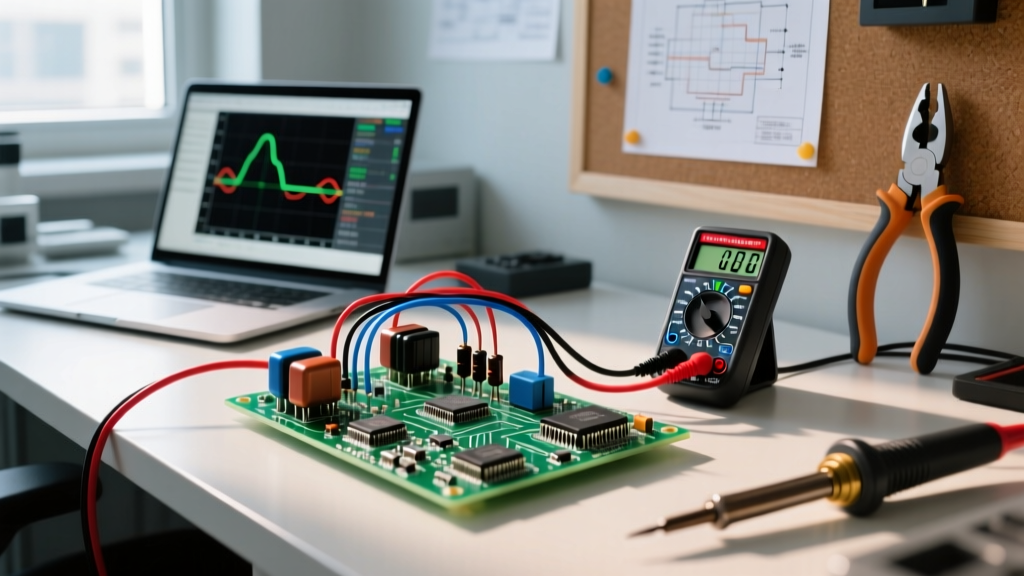
If you need a diode with a low forward voltage drop (0.15V to 0.45V) and ultra-fast switching speeds, you need a Schottky diode (Note: While frequently misspelled as "shotkky diode" in forum searches, the correct spelling is Schottky, named after physicist Walter H. Schottky). Unlike standard PN-junction diodes that use two semiconductor materials, a Schottky diode uses a metal-semiconductor junction. This physical difference eliminates minority carrier storage time, making it the mandatory choice for high-frequency switching power supplies, reverse polarity protection, and RF clamping.
For immediate bench use: default to the 1N5819 for 1A/40V through-hole applications, the SS14 for 1A surface-mount, and the 1N5822 for 3A/40V power rectification. Below is the complete decision framework, circuit implementation, and testing procedure to ensure you select and deploy the right part without burning up your board.
The Core Advantage: Symbol, Pinout, and Physical ID
Before soldering, you must correctly identify the pins. A reversed Schottky in a power path will result in a dead short and catastrophic failure.
Schematic Symbol and Pin Names
The schematic symbol resembles a standard diode (a triangle pointing toward a vertical line), but the vertical line has bent "hooks" at the top and bottom, or sometimes an "S" overlaid on it.
- Anode (A): The positive terminal. Current flows into this pin. Represented by the flat base of the triangle.
- Cathode (K): The negative terminal. Current flows out of this pin. Represented by the modified vertical line.
Physical Identification
On through-hole axial packages (like the DO-41 or DO-201AD), the Cathode is marked with a distinct printed band on the body. For SMD packages (like SMA or SMB), the cathode is marked with a thick white or gray band on the plastic molding. Always verify with a datasheet; some SMD signal diodes use subtle laser codes rather than a full band.
Operation Regions and Electrical Limits
The trade-off for a low forward voltage drop ($V_F$) is high reverse leakage current ($I_R$). Understanding these operation regions is critical to preventing thermal runaway.
| Operation Region | Voltage Condition | Current Behavior | Typical Values (e.g., 1N5819) |
|---|---|---|---|
| Forward Bias | $V_A > V_K$ by at least $V_F$ | Current flows freely. $V_F$ increases logarithmically with current. | $V_F$ = 0.20V @ 100mA $V_F$ = 0.60V @ 1.0A (max) |
| Reverse Bias | $V_K > V_A$ (below $V_{RRM}$) | Blocks current, but significant leakage flows due to the metal-semiconductor junction. | $I_R$ = 1.0mA @ 20V $I_R$ = 10mA @ 40V (at 25°C) |
| Thermal Runaway Zone | High Reverse Voltage + High Temp | Reverse leakage doubles roughly every 10°C. Power dissipation ($V_R \times I_R$) causes self-heating. | $I_R$ can exceed 50mA at 100°C, leading to thermal destruction. |
| Breakdown | $V_K > V_A$ (exceeds $V_{RRM}$) | Avalanche breakdown. Unlike Zeners, standard Schottkys are not rated to survive this. | $V_{RRM}$ (Peak Repetitive Reverse Voltage) = 40V for 1N5819. |
Decision Path: Selecting the Right Schottky for the Job
Use this decision tree to terminate your part selection process with a concrete pick. Do not over-engineer; stick to the safe defaults unless your specific constraints demand otherwise.
| If your application requires... | Then select this category... | Concrete Default Part Number |
|---|---|---|
| Signal clamping, GPIO protection, or RF mixing (< 200mA) | Small Signal SMD Schottky | BAT54 (SOT-23, 30V, 200mA) |
| Reverse polarity protection or low-current rectification (< 1A) | 1A Power Schottky (Through-hole or SMA) | 1N5819 (DO-41) or SS14 (SMA) |
| Freewheeling diode for 1A to 3A switching regulators | 3A Power Schottky (DO-201AD or SMB) | 1N5822 (DO-201AD) or SS34 (SMB) |
| High current (> 5A) or High Voltage (> 60V) | STOP. Schottkys are the wrong tool. | Use UF5408 (Ultrafast) or a Synchronous MOSFET. |
Application Circuit: 12V-to-5V Buck Converter Freewheeling Diode
The most common use for a power Schottky diode is as a freewheeling (flyback) diode in a step-down (buck) switching regulator. When the internal MOSFET of the regulator turns off, the inductor's magnetic field collapses, generating a reverse voltage spike. The Schottky diode provides a low-loss path for this inductor current to keep flowing to the load.
Circuit Specifications
- IC: Texas Instruments LM2596 (150kHz, 3A Step-Down Regulator)
- Input Voltage: 12V DC
- Output Voltage: 5.0V DC @ 3A max
- Schottky Diode: 1N5822 (3A, 40V)
Component Values and Wiring
- Input Capacitor (C1): 680µF, 25V Low-ESR Aluminum Electrolytic. Place as close to the VIN pin as possible.
- Inductor (L1): 33µH, rated for at least 4A saturation current. Connect between the OUTPUT pin and the load.
- Schottky Diode (D1): Connect the Cathode to the OUTPUT pin (the switch node). Connect the Anode to the system Ground.
- Output Capacitor (C2): 680µF, 10V Low-ESR. Connect between the load side of the inductor and Ground.
Failure Modes and Multimeter Testing Procedures
Schottky diodes generally fail in two ways: short circuit (due to overvoltage transients exceeding $V_{RRM}$) or thermal runaway (due to excessive reverse leakage at high temperatures). Here is how to verify a diode's health using a standard digital multimeter (DMM).
Step-by-Step Multimeter Testing
Note: For accurate results, desolder at least one leg of the diode from the circuit. Testing in-circuit can yield false readings due to parallel inductors or capacitors.
- Set the DMM: Turn the dial to the "Diode Test" mode (usually indicated by a diode symbol and a sound wave icon).
- Forward Bias Test: Place the Red probe on the Anode and the Black probe on the Cathode.
- Expected Reading: 0.200V to 0.450V. This is the forward voltage drop. If it reads 0.600V+, you are likely testing a standard silicon PN diode, not a Schottky.
- Reverse Bias Test: Swap the probes. Place the Black probe on the Anode and the Red probe on the Cathode.
- Expected Reading: "OL" (Over Limit) or "1" on the far left of the display. This confirms the diode is blocking reverse current.
- Diagnose the Results:
- Reads ~0.00V in both directions: The diode is shorted. Replace it.
- Reads "OL" in both directions: The diode is open (internal bond wire melted). Replace it.
- Reads a low voltage (e.g., 0.10V) in reverse bias: The junction is leaking heavily and is degraded. Replace it.
The "Safe Default" Part Numbers for Your Bench
Stop wasting time evaluating obscure alternatives for 95% of your projects. Stock your bench with these specific, widely available Vishay and Diodes Inc. parts. They offer the best balance of price, availability, and reliable datasheet specifications.
| Part Number | Package | Max $I_F$ | Max $V_{RRM}$ | Typical $V_F$ @ $I_F$ | Best Use Case |
|---|---|---|---|---|---|
| BAT54 | SOT-23 (SMD) | 200mA | 30V | 0.35V @ 100mA | Microcontroller GPIO clamping, RF signal mixing. |
| 1N5817 | DO-41 (Axial) | 1.0A | 20V | 0.32V @ 1.0A | Low-voltage (5V/12V) reverse polarity protection. |
| 1N5819 | DO-41 (Axial) | 1.0A | 40V | 0.40V @ 1.0A | General purpose 1A rectification, solar panel bypass. |
| SS14 | DO-214AC / SMA | 1.0A | 40V | 0.50V @ 1.0A | SMD equivalent to 1N5819 for compact power boards. |
| 1N5822 | DO-201AD (Axial) | 3.0A | 40V | 0.55V @ 3.0A | Freewheeling diode for LM2596 and similar 3A bucks. |
| SS34 | DO-214AB / SMC | 3.0A | 40V | 0.55V @ 3.0A | SMD equivalent to 1N5822 for automated assembly. |
The Final Verdict: If you are building a DC-DC buck converter under 3A, buy a bulk pack of 1N5822 (through-hole) or SS34 (SMD). If you are protecting a 12V lead-acid battery circuit or an Arduino power input from reverse polarity, use the 1N5819. Keep these six part numbers in your kit, and you will have the correct Schottky diode for virtually any hobbyist or prototyping power application you encounter.