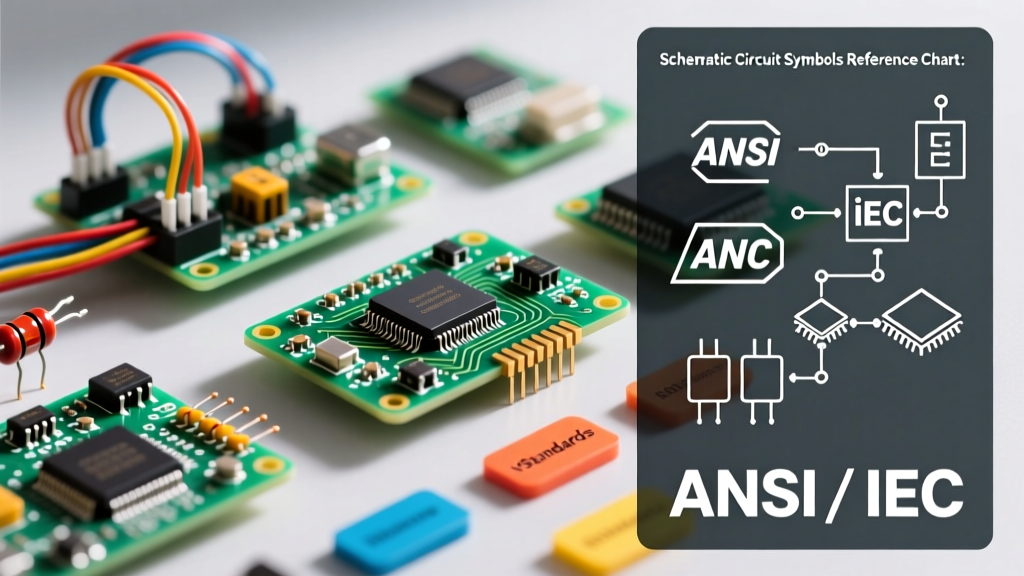

The Master Schematic Circuit Symbols Reference Table
The table below maps the most common components you will encounter on a workbench. Pay close attention to the polarization and terminal markers, as misinterpreting these is the leading cause of reversed-bias failures.
| Component | ANSI/IEEE (US) Symbol | IEC (EU/Global) Symbol | Practical Meaning & Bench Notes |
|---|---|---|---|
| Resistor | Zig-zag line | Empty rectangle | IEC rectangles can look like ICs if pin counts are not explicitly drawn. Always check the reference designator (R vs U). |
| Capacitor (Non-polarized) | Two parallel straight lines | Two parallel straight lines | Used for decoupling and AC coupling. No polarity means you cannot install it backward. |
| Capacitor (Polarized) | One straight line, one curved line | Two parallel lines with a '+' sign | In ANSI, the curved line is ALWAYS the negative/ground side. Reversing electrolytics causes venting or explosion. |
| Inductor / Coil | Series of looping humps | Series of looping humps | Watch for dots indicating phase/polarity on coupled inductors and transformers. |
| Diode | Triangle pointing to a vertical line | Triangle pointing to a vertical line | Current flows from the flat back (anode) to the line (cathode). The line matches the physical stripe on the component body. |
| NPN BJT Transistor | Circle with arrow pointing OUT | Circle with arrow pointing OUT | Arrow points out for NPN (Not Pointing iN). Emitter is the arrow, Collector is the straight line. |
| N-Channel MOSFET | Line with arrow pointing IN (or dashed line) | Line with arrow pointing IN (or dashed line) | Dashed channel line means Enhancement mode (normally off). Solid line means Depletion mode (normally on). |
| SPST Switch | Line breaking into a hinged lever | Line breaking into a hinged lever | Single Pole, Single Throw. The open circle represents the contact terminal. |
| Relay Coil | Rectangle with diagonal lines or 'K' designator | Rectangle with diagonal lines | The coil is drawn separately from the switch contacts it actuates. Trace the reference designator (e.g., K1) to find the contacts. |
Regional Standard Variants: ANSI/IEEE vs. IEC vs. Old UK
Schematic circuit symbols are not universally identical. The governing body that authored the schematic dictates the visual language. If you are repairing imported gear or collaborating internationally, you must know which standard you are looking at.
- ANSI/IEEE Std 315 (North America): Dominates the US and Canada. Recognizable by zig-zag resistors, curved-plate polarized capacitors, and explicit component outlines. If you are reading a schematic from a US-based manufacturer like Tektronix or Fender, you are reading IEEE 315.
- IEC 60617 (Europe & Global): The international standard adopted by the EU, Asia, and most modern global CAD software defaults. Recognizable by rectangular resistors, simpler logic gate outlines, and standardized terminal numbering. All About Circuits provides an excellent breakdown of how modern CAD tools default to IEC for global compatibility.
- BS 3939 (Old UK): Largely obsolete and replaced by IEC, but you will still encounter it in vintage British audio equipment (like early Quad or Leak amplifiers) and 1960s military radios. It features unique variations for valves (tubes) and older transformer notations that do not map cleanly to modern IEC symbols.
Rows People Get Wrong (and Decoding Faded Schematics)
Even experienced technicians misread specific schematic circuit symbols, especially when dealing with degraded documentation or ambiguous PCB silkscreens.
The Ground Symbol Confusion
There are three distinct ground symbols, and treating them as interchangeable will cause noise issues or safety hazards:
- Signal Ground (Downward Triangle): The local 0V reference for low-voltage analog/digital signals. This is your ESP32 GND pin.
- Chassis Ground (Three Decreasing Horizontal Lines): Connects to the physical metal enclosure. Used for shielding and returning high-current noise away from sensitive signal paths.
- Earth Ground (Three Lines with Ground Stakes): The literal connection to dirt via a copper ground rod. This is the green wire in your AC mains cable. It exists purely for human safety and fault clearing.
Safe Interpretation of Faded or Missing Markings
When a schematic is water-damaged, or the PCB silkscreen has flaked off a 30-year-old board, you cannot rely on the printed symbols. You must verify the physical component behavior using a multimeter.
- Faded Semiconductor Symbols: If you suspect a faded symbol is a diode or a BJT base-emitter junction, use your DMM's diode-test mode. A standard silicon junction will read a 0.5V to 0.7V forward voltage drop. A Schottky diode will read 0.2V to 0.3V. If it reads 'OL' in both directions, the junction is blown open.
- Missing Polarization Marks: If the '+' symbol on a polarized capacitor is faded, look for the physical component. Electrolytic capacitors have a painted stripe with minus signs indicating the negative lead. Tantalum capacitors use a painted stripe or a '+' mark to indicate the POSITIVE lead. Mixing these up based on a faded schematic assumption will result in a short circuit.
- Trace the Copper: When schematic circuit symbols for IC pins are completely illegible, identify the decoupling capacitors (0.1µF ceramics). One side of these caps is always tied to VCC and the other to GND. This gives you an immediate, reliable reference point to map the rest of the IC pins against the manufacturer's datasheet.
Schematic Circuit Symbols FAQ
What do the dots at wire intersections mean in schematic circuit symbols?
A solid dot at a wire intersection means the wires are electrically connected (a node). If two wires cross without a dot, or if one wire 'hops' over the other using a semicircular arc, they are not connected. Note that modern CAD software (like KiCad or Altium) has largely abandoned the 'hop' convention to avoid ambiguity; in modern schematics, no dot always means no connection, and a dot always means a connection.
Why does my European schematic use rectangles for resistors instead of zig-zags?
This is the hallmark of the IEC 60617 standard, which is mandatory in most of Europe and widely used in international manufacturing. The IEC committee standardized on rectangles for all passive, non-reactive components to simplify automated schematic drafting and reduce visual clutter. If you see rectangular resistors, you are looking at an IEC-compliant diagram, and you should expect IEC logic gate and transistor symbols elsewhere on the page.
How do I identify an unmarked IC pinout when the schematic circuit symbols are missing?
When the schematic is lost and the IC top marking is sanded off, start by identifying the power rails using the decoupling capacitors as mentioned above. Next, look for pull-up resistors (usually 4.7kΩ or 10kΩ) tracing to I2C lines (SDA/SCL). For microcontrollers, locate the crystal oscillator; the two pins connected to the crystal and its load capacitors are your XTAL1 and XTAL2 pins. Cross-reference these physical landmarks with the suspected IC's datasheet to confirm the part number.
What is the difference between the chassis ground and earth ground symbols?
Chassis ground (the three decreasing horizontal lines) is a local reference tied to the metal frame of the device, used primarily for EMI shielding and structural return paths. Earth ground (the lines with vertical stakes) is a safety bond connected to the physical earth via the building's wiring. In a properly designed Class I appliance, the chassis ground is bonded to the earth ground at exactly one point to ensure that if a live mains wire touches the metal case, the breaker trips immediately rather than electrocuting the user.


