What Is a Resistor—and Why Does It Matter?
A resistor is the most fundamental passive component in electronics. Its sole purpose is to oppose the flow of electric current, converting electrical energy into heat. Unlike capacitors or inductors, it does not store energy—it dissipates it predictably and reliably. Every working circuit—from a simple LED blinker on an Arduino Uno to the voltage regulation stage inside a MacBook Pro’s power management IC—depends on resistors to set current limits, divide voltages, pull signals high or low, and terminate transmission lines. Without resistors, integrated circuits would overheat, LEDs would burn out instantly, and microcontrollers would misread sensor inputs. For beginners, mastering resistors isn’t optional—it’s the essential first step toward building, debugging, and understanding any electronic system.
How Resistors Work: Ohm’s Law Made Practical
Georg Ohm’s 1827 discovery remains the bedrock of resistor behavior: V = I × R, where voltage (V) across a resistor equals the current (I) flowing through it multiplied by its resistance (R). This linear relationship holds true for most common resistors at room temperature and within their rated power limits. For example, if a 330 Ω resistor carries 15 mA of current, the voltage drop across it is exactly 4.95 V (0.015 A × 330 Ω). This principle lets you calculate unknown values in real time—whether sizing a current-limiting resistor for a 2.1 V red LED powered by a 5 V Arduino pin or determining how much voltage remains for a sensor after passing through a voltage divider.
Real-World Example: LED Current Limiting
Consider a common 5 mm red LED with a forward voltage (Vf) of 2.0 V and a recommended forward current (If) of 20 mA. Powered from a 5 V supply, the resistor must drop the remaining 3.0 V while limiting current to 20 mA. Applying Ohm’s Law: R = (5 V − 2.0 V) ÷ 0.020 A = 150 Ω. Standard E24 series offers 150 Ω as a precise value—so no interpolation needed. In practice, engineers often choose the next higher standard value (e.g., 180 Ω) for margin, yielding 16.7 mA—still bright, but safer for long-term operation.
Reading Resistor Values: Color Codes and Markings
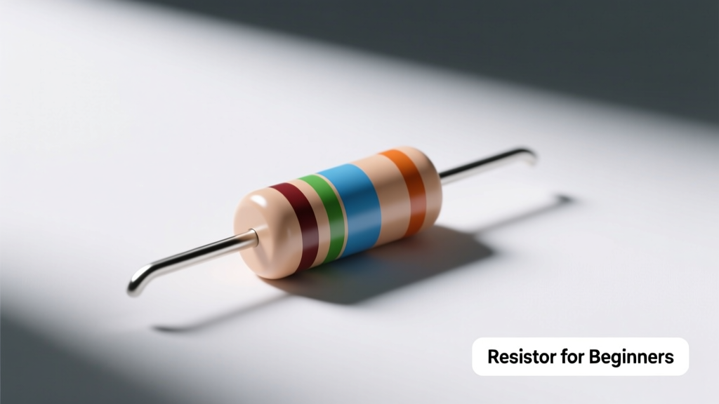
Through-hole resistors use color bands; surface-mount devices (SMD) use alphanumeric codes. A four-band axial resistor encodes value as follows: Band 1 = first digit, Band 2 = second digit, Band 3 = multiplier (power of ten), Band 4 = tolerance. For instance, brown-black-red-gold translates to 1-0 × 10² = 1,000 Ω (1 kΩ), ±5%. A five-band version adds a third significant digit—for greater precision—such as red-red-black-brown-brown = 2-2-0 × 10¹ = 2,200 Ω (2.2 kΩ), ±1%.
SMD Resistor Codes Explained
SMD resistors use three-digit codes for values under 10 MΩ. The first two digits are significant figures; the third is the multiplier (number of zeros). So '103' means 10 × 10³ = 10,000 Ω (10 kΩ). 'R22' indicates 0.22 Ω (the 'R' replaces the decimal point). For 1% tolerance parts, a four-digit code appears—'1002' means 100 × 10² = 10,000 Ω. Leading manufacturers like Yageo (RC series) and Panasonic (ERJ series) print these directly on 0805 and 1206 packages, which measure 2.0 mm × 1.25 mm and 3.2 mm × 1.6 mm respectively.
Standard Resistor Values and Series
Resistors aren’t manufactured in arbitrary values—they follow internationally standardized decades defined by the IEC 60063 standard. The E12 series provides 12 values per decade (e.g., 10, 12, 15, 18, 22, 27, 33, 39, 47, 56, 68, 82 Ω), suitable for general-purpose applications with ±10% tolerance. The tighter E24 series adds 12 more values (e.g., 11, 13, 16, 20, 24, 27, 30, 36, 43, 51, 62, 75 Ω) for ±5% parts. Precision designs use E48 (±2%), E96 (±1%), or E192 (±0.5%) series. For example, a Bourns CFR-25 series 1% metal film resistor comes in E96 values—including 4.99 kΩ, 7.87 kΩ, and 9.76 kΩ—not just round numbers.
Why Standardization Matters
Standardization reduces inventory complexity and improves manufacturing yield. If every design required custom values, prototyping would slow dramatically, and cost per unit would rise. Consider this: Vishay’s CRCW series—among the world’s best-selling thick-film SMD resistors—offers over 12,000 distinct values across E24 and E96, all stocked by major distributors like Digi-Key and Mouser. That breadth means you can almost always find a resistor that meets your precision and power needs without special ordering.
Key Specifications Beyond Resistance Value
Five parameters define a resistor’s suitability for a given application:
- Resistance value (in ohms, Ω): The nominal opposition to current flow.
- Tolerance: The allowable deviation from nominal value—typically ±1%, ±5%, or ±10%. A 10 kΩ ±5% resistor may measure anywhere from 9.5 kΩ to 10.5 kΩ.
- Power rating: Maximum continuous power dissipation without damage. Common ratings are 1/8 W (0.125 W), 1/4 W (0.25 W), 1/2 W (0.5 W), and 1 W. Exceeding this causes overheating and resistance drift—or catastrophic failure.
- Temperature coefficient (TCR): How much resistance changes per degree Celsius (ppm/°C). Carbon film parts average ±350 ppm/°C; metal film types like KOA Speer’s PR02 series achieve ±25 ppm/°C.
- Maximum operating voltage: Voltage limit before arcing or insulation breakdown. A typical 1/4 W axial resistor has a max voltage rating of 200–350 V DC, while high-voltage models (e.g., Caddock MG series) exceed 10 kV.
Common Resistor Types Compared
Not all resistors behave the same way—even at identical values. Material and construction dictate performance in critical areas like stability, noise, and frequency response.
| Type | Typical Tolerance | TCR (ppm/°C) | Max Power (common) | Key Applications | Example Brands & Series |
|---|---|---|---|---|---|
| Carbon Composition | ±5% to ±20% | −1,200 to −500 | 0.125–2 W | Vintage audio repair, surge protection | Ohmite OX series |
| Carbon Film | ±5% | ±500 | 0.125–2 W | General-purpose prototyping, consumer electronics | Vishay CN series, TE Connectivity CFN |
| Metal Film | ±0.1% to ±1% | ±25 to ±100 | 0.125–3 W | Precision analog circuits, instrumentation, power supplies | Bourns PFC, KOA Speer PR02, Vishay CMF |
| Thick-Film SMD | ±1% to ±5% | ±100 to ±200 | 0.0625–1 W | High-volume PCBs (smartphones, laptops, IoT sensors) | Yageo RC series, Panasonic ERJ series |
| Wirewound | ±0.1% to ±5% | ±20 to ±100 | 1–100 W | High-power loads, current sensing, industrial controls | Vishay WSHP, Caddock TS series |
For beginners, metal film (e.g., Bourns PFC-1001 series, 1% tolerance, 0.25 W, 100 ppm/°C) offers the best balance of accuracy, stability, affordability, and availability. Avoid carbon composition unless restoring tube amplifiers—their high noise and poor stability make them unsuitable for modern digital or mixed-signal designs.
Power Rating: Calculating and Selecting Safely
Power dissipation is calculated using P = I² × R or P = V² ÷ R. A resistor running near its rated power will get noticeably warm—a useful tactile diagnostic. But sustained operation above 70% of rating shortens lifespan and risks drift. Let’s say a 1 kΩ resistor drops 12 V in a power supply feedback network. Power dissipated is (12 V)² ÷ 1,000 Ω = 0.144 W. While a 1/8 W (0.125 W) part could technically handle it, derating practice dictates choosing at least a 1/4 W (0.25 W) unit—providing 74% headroom. Vishay’s datasheets explicitly recommend ≤70% of rated power for >10,000-hour reliability in commercial environments.
When Power Ratings Lie
Rated power assumes free-air convection at 70°C ambient. On a densely packed PCB with limited airflow—like inside a Raspberry Pi 4 case—derating is mandatory. IPC-2221 guidelines suggest reducing rated power by 20% for board-mounted resistors in enclosed spaces. That same 1/4 W resistor may only safely dissipate 0.20 W in such conditions. Always consult manufacturer derating curves: for example, KOA Speer’s PR02 series shows 50% power reduction at 105°C ambient.
Practical Tips for Beginners
Start simple—and build confidence methodically. Here’s what works:
- Begin with a curated kit: The Elegoo Electronics Fun Kit includes 640 pieces across 23 standard values (10 Ω to 1 MΩ), all 1/4 W carbon film with 5% tolerance—ideal for learning Ohm’s Law, voltage dividers, and basic sensor interfacing.
- Use a multimeter religiously: Before inserting any resistor into a circuit, verify its actual value. Even new 5% parts can read ±4.8%—and aging components drift further. A Fluke 117 or Brymen BM869s delivers 0.05% basic accuracy on resistance ranges.
- Label your storage: Resistors look identical when loose. Use labeled anti-static tubes (e.g., Stack-On ST-24) or compartmentalized boxes (like the Akro-Mils 2128D) with printed E24/E96 charts taped inside.
- Avoid substitution traps: Never swap a 1/2 W resistor for a 1/4 W unit just because values match—thermal mass and surface area differ drastically. Likewise, don’t replace a metal film part with carbon film in a precision op-amp circuit—the increased noise and TCR will degrade signal integrity.
- Read datasheets—not just packaging: A ‘10 kΩ’ label tells only part of the story. The Vishay CRCW08051002FRT1’s full specs include: 10 kΩ ±1%, 0.125 W, 200 V max, TCR ±100 ppm/°C, and 1000-hour load life at 70°C. That last figure matters—if your project runs continuously for years, longevity data beats marketing copy every time.
One often-overlooked reality: resistor leads matter. Axial carbon film resistors (e.g., Vishay CN series) have tinned copper leads with 0.6 mm diameter—compatible with standard breadboards and 0.025″ pitch perfboard. But SMD resistors require soldering skill and fine-tip irons (like the Quick 861DW, 650°F max). Beginners should master through-hole assembly first—then transition to SMD once comfortable with thermal management and magnification tools.
Finally, recognize that resistors interact with other components. A 10 MΩ pull-up resistor may work perfectly with a CMOS microcontroller input—but fail miserably with an old-school 74LS TTL gate, whose input leakage current (up to 400 µA) would drag the voltage below logic-high thresholds. Always cross-check interface specifications: the Texas Instruments SN74LVC1G08 datasheet specifies maximum input leakage of ±10 µA—making 10 MΩ viable—while the classic 74LS08 demands ≤1 kΩ for reliable operation.
Understanding resistors isn’t about memorizing formulas—it’s about developing intuition. When you see a 470 Ω resistor feeding an NPN transistor base, you immediately think: “That’s limiting base current to ~10 mA at 5 V, giving ~2 mA collector drive assuming β = 200.” When you spot a 0.1 Ω shunt resistor in a motor driver schematic, you know it’s for current sensing—and that even 1% tolerance means ±1 mΩ error, translating to ±100 mA uncertainty at 10 A. That fluency emerges only with deliberate practice, measurement, and repeated circuit validation.
Resistors teach humility: they’re simple, yet demand respect for physics. Their value tolerances, thermal limits, and material quirks shape real-world behavior far more than idealized schematics suggest. But that’s also their beauty—they’re honest. A resistor never lies about current or voltage. It simply obeys Ohm’s Law—every single time. And for beginners, that consistency is the perfect foundation.
Manufacturers invest heavily in consistency. Bourns’ PFC series undergoes 100% electrical testing at 25°C and 70°C; Yageo’s RC0805JR-0710KL is subjected to 1,000-hour high-temperature storage tests at 155°C to validate long-term stability. These aren’t academic exercises—they’re assurances that the 10 kΩ resistor you buy today will still be 10 kΩ five years from now, mounted on your weather station PCB in Arizona summer heat.
Don’t rush past resistors thinking they’re ‘too basic’. They anchor every meaningful interaction between silicon and the physical world. Whether setting gain in an instrumentation amplifier, biasing a MOSFET gate, or calibrating a thermistor network, resistors define boundaries, enable control, and enforce safety. Master them—not as static components, but as dynamic, measurable, predictable partners in every circuit you build.
As you progress, explore advanced variants: zero-ohm jumpers (e.g., Yageo RC0402JR-070RL) for configurable PCB traces; fusible resistors (e.g., Littelfuse NFR2000) that open under overload; or thermistors (e.g., Murata NCP15XH103) whose resistance changes with temperature. But start grounded—literally and figuratively—with the humble resistor. Measure it. Calculate it. Respect its limits. Then build outward—confidently, accurately, and correctly.
Remember: the difference between a working prototype and a smoking board often comes down to one overlooked resistor—selected for convenience instead of calculation, rated for power instead of margin, or substituted without checking TCR. Avoid those pitfalls by treating every resistor as intentional, verified, and documented. Your future self—debugging at 2 a.m.—will thank you.