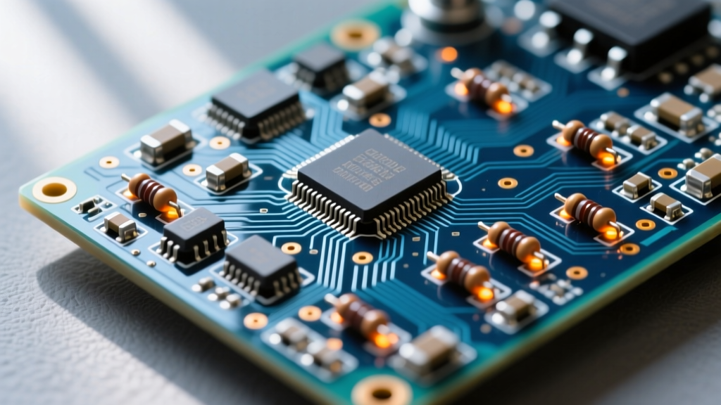

Resistivity temperature, formally quantified as the Temperature Coefficient of Resistance (TCR), dictates how a material's opposition to current flow changes as it heats up. In power electronics, this is not just an academic curiosity; it is the physical trigger for thermal runaway. As a conductor or semiconductor junction heats up, its resistivity typically increases. This higher resistance causes greater I²R (copper) losses, which generates more heat, further increasing resistance in a destructive positive feedback loop. To prevent your boards from melting or silicon from failing, you must design your thermal management system around the worst-case resistivity temperature shift, not the 25°C datasheet baseline.
The Physics of Resistivity Temperature and Thermal Runaway
The relationship between temperature and resistance is modeled by the linear approximation formula: R(T) = R₀[1 + α(T - T₀)], where α is the TCR. For pure metals like copper and aluminum, α is positive. For silicon-based power MOSFETs, the effective TCR of the drain-source on-resistance (R_DS(on)) is also heavily positive because carrier mobility degrades as lattice vibrations increase at higher temperatures.
A common beginner mistake is sizing traces and heatsinks based on the 25°C R_DS(on) value. If a MOSFET has an R_DS(on) of 10 mΩ at 25°C, it will typically exhibit 20 mΩ to 22 mΩ at a 150°C junction temperature. If your thermal design only accounts for the 10 mΩ baseline, your actual power dissipation will double as the part heats up, rapidly pushing the junction past its absolute maximum ratings.
| Material / Component | TCR (α) at 20°C | Base Resistivity / R_DS(on) | Typical Thermal Limit | Primary Failure Mode if Exceeded |
|---|---|---|---|---|
| Copper (PCB Trace) | +3,930 ppm/°C | 1.68 μΩ·cm | 105°C (FR4 Tg limit) | Dielectric delamination, trace lifting |
| Aluminum (Busbar/Heatsink) | +2,300 ppm/°C | 2.65 μΩ·cm | 150°C | Mechanical creep at bolted joints |
| Si MOSFET (R_DS(on)) | +6,000 ppm/°C (eff.) | Datasheet specific | 175°C (T_J max) | Bond wire melt, intrinsic silicon failure |
| Nichrome (NiCr Heater) | +400 ppm/°C | 110 μΩ·cm | 1200°C | Oxidation and brittle mechanical fracture |
Because silicon MOSFETs have a positive resistivity temperature coefficient, they naturally current-share when placed in parallel; the hotter device increases in resistance, shifting current to the cooler device. Conversely, Bipolar Junction Transistors (BJTs) have a negative TCR for their collector-emitter saturation voltage. If you parallel BJTs without strict emitter ballast resistors, the hotter BJT will draw more current, leading to immediate secondary breakdown and thermal runaway.
Calculating the Thermal Path: From Junction to Ambient
To manage the resistivity temperature shift, you must calculate the steady-state junction temperature (T_J). The thermal path is modeled as a series of thermal resistances (R_θ), measured in °C/W, analogous to electrical resistance in Ohm's law.
The governing equation is:
T_J = T_A + P_D × (R_θJC + R_θCS + R_θSA)
- T_A: Ambient temperature inside the enclosure (not just the room).
- P_D: Power dissipation (calculated using the worst-case hot R_DS(on), not the 25°C value).
- R_θJC: Junction-to-case thermal resistance (fixed by the silicon die and package).
- R_θCS: Case-to-sink thermal resistance (determined by your thermal interface material).
- R_θSA: Sink-to-ambient thermal resistance (determined by your heatsink and airflow).
Interpreting the Derating Curve
Semiconductor datasheets include a power derating curve. For a classic TO-247 packaged IRFP460 MOSFET, the datasheet claims a massive 280W power dissipation capability. However, this assumes the case temperature is held at exactly 25°C, which requires an infinite heatsink or liquid cold plate. The derating curve slopes downward at a rate of roughly 1.2 W/°C (which is the inverse of the 0.83 °C/W R_θJC). By the time your case temperature reaches 100°C, the allowable power dissipation has dropped to roughly 140W. If your resistivity temperature math ignores this curve, your design will fail under continuous load.
Heatsink Selection and Airflow: Sizing for the Worst Case
Let us run a real-world heatsink selection for a 20W continuous dissipation load using an IRFP460 in a TO-247 package. We want to keep the junction temperature (T_J) below 125°C to maintain reliability, and our enclosure ambient (T_A) is 40°C.
Assumptions:
- P_D = 20W (calculated using 150°C R_DS(on) to account for resistivity temperature rise)
- R_θJC = 0.83 °C/W (from datasheet)
- R_θCS = 0.50 °C/W (using a standard 0.25mm silicone thermal pad like Bergquist Sil-Pad 2000)
The Math:
125°C = 40°C + 20W × (0.83 + 0.50 + R_θSA)
85 = 20 × (1.33 + R_θSA)
4.25 = 1.33 + R_θSA
R_θSA = 2.92 °C/W
You need a heatsink with a sink-to-ambient thermal resistance of 2.92 °C/W or lower. A standard extruded aluminum profile like the Boyd (Aavid) 577202B03900G provides an R_θSA of roughly 2.5 °C/W in natural convection (still air). This works, but leaves very little margin for dust buildup or higher summer ambient temperatures.
What Airflow and Enclosure Changes Buy You
If you add a small 40mm exhaust fan (such as a Noctua NF-A4x20) to force air across the fins at 200 Linear Feet per Minute (LFM), the R_θSA of that same Boyd heatsink drops to approximately 1.2 °C/W. This cuts your thermal resistance in half, dropping the junction temperature to roughly 90°C. Conversely, if you seal the enclosure for IP65 dust/water resistance without adding external fins, you introduce an enclosure-to-ambient resistance (R_θCA) that can easily add 3.0 °C/W to your total path, guaranteeing thermal shutdown. According to thermal management guidelines published by Electronics Cooling, transitioning from natural convection to forced air is the most cost-effective way to combat resistivity-induced thermal runaway in sealed power systems.
Failure Signatures: How Hot is Too Hot?
Silicon dies are typically rated for a maximum junction temperature (T_J max) of 150°C or 175°C. However, 100°C is the practical reliability limit. The Arrhenius equation dictates that the operational lifespan of electronic components halves for every 10°C increase above a baseline of roughly 70°C. Running a MOSFET at 160°C will not instantly destroy the silicon, but it will drastically accelerate mechanical and chemical failure mechanisms.
When diagnosing a failed power board, look for these specific failure signatures of thermal stress:
- Solder Joint Creep and Fatigue: Repeated thermal cycling causes the solder at the toe and heel of TO-247 or D2PAK leads to undergo creep. You will see microscopic cracking under magnification, leading to intermittent high-resistance connections that exacerbate the resistivity temperature feedback loop.
- Die Attach Delamination: The solder or sintered silver attaching the silicon die to the copper leadframe degrades. On a thermal camera, this appears as an asymmetrical 'hot spot' on the package surface, because the heat cannot transfer evenly to the heatsink.
- Bond Wire Lift-Off: The thin aluminum wires connecting the silicon die to the package pins expand and contract at different rates than the silicon. Over time, the wedge bonds lift off, resulting in an open-circuit failure.
- PCB Tg Exceedance: If the copper traces heat past the glass transition temperature (Tg) of the FR4 substrate (typically 130°C to 170°C), the PCB resin softens. The copper traces will physically peel away from the board under mechanical stress.
Never assume your heatsink is working by touching the fins. A poorly torqued mounting clip or a dried-out thermal pad can result in a massive R_θCS bottleneck. The heatsink might feel barely warm to the touch while the MOSFET case is sitting at 140°C. Always use a thermocouple or IR camera to measure the actual case temperature (T_C) during prototype validation, and verify it against your T_J math. For deeper insights into package-level thermal resistance, refer to the Analog Devices thermal management guidelines.
Managing resistivity temperature is not about keeping components at room temperature; it is about ensuring the positive feedback loop of resistance and heat is broken by a sufficiently low-impedance thermal path to the ambient environment. Calculate your R_θ stack-up using worst-case hot resistance values, select your heatsink based on forced-air derating if necessary, and keep your steady-state junctions well below the silicon absolute maximums to ensure long-term reliability.


