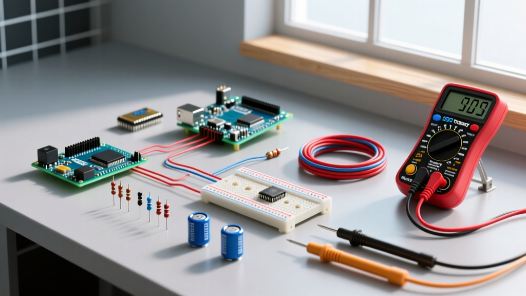
The "function fuse" in an electromechanical control circuit serves strictly as the overcurrent protective device, while the relay or contactor handles the daily switching function. To design this correctly, the contactor's utilization category (like AC-3) governs the continuous motor load, while the upstream function fuse's interrupting rating (kAIC) and time-current curve must safely clear fault conditions without nuisance tripping. Below is the exact framework for selecting, wiring, and testing these paired components on the bench or in the panel.
The Core Distinction: Switching Function vs. Function Fuse Protection
Beginners often conflate the roles of electromechanical switches and overcurrent protection. A contactor (like the widely used Schneider TeSys line) or a control relay (like an Omron G2R) is designed to make and break normal operating currents. Its contacts are rated for a specific number of mechanical and electrical cycles under load.
The function fuse, conversely, sits dormant during normal operation. Its sole job is to vaporize its internal element and clear the circuit during a short-circuit or severe overload.
Never swap a specified function fuse for a miniature circuit breaker (MCB) without analyzing the time-current curves. A fuse clears high-magnitude faults in milliseconds via its $I^2t$ melting integral, limiting let-through energy. An MCB relies on a thermal-magnetic trip curve; its mechanical unlatching time allows significantly more destructive thermal and magnetic energy to pass through to the contactor contacts during a dead short, potentially welding them shut.
Decoding Electromechanical Ratings: Coil, Contact, and Breaking Capacity
When reading a datasheet for an electromechanical component, you are looking at three distinct electrical boundaries. Here is how they map to real-world 2026 component specifications (using a standard 9A IEC contactor and a 10A PCB relay as baselines).
| Parameter | Typical Value (Contactor / Relay) | Definition | What It Governs |
|---|---|---|---|
| Coil Voltage | 24VDC / 120VAC | The control voltage required to pull in the armature and hold it closed. | The control circuit design and power supply sizing. |
| Contact Rating | 9A (AC-3) / 10A (Resistive) | The maximum continuous current the main contacts can carry and switch at a specific voltage and load type. | The steady-state running current of your load. |
| Breaking Capacity | 6kA / 10A (N/A for fault) | The maximum fault current the device can safely interrupt without exploding or welding. | Coordination with the upstream function fuse. |
Which Rating Column Governs This Load?
The Contact Rating column—specifically the IEC Utilization Category—governs your continuous load. If you are switching a 5A squirrel-cage motor, you must look at the AC-3 rating (which accounts for 6x inrush current), not the AC-1 (resistive) rating. The function fuse's ampacity governs the wire protection, while its kAIC rating governs the fault protection.
Load Type Decision Path: Resistive, Inductive, and Motor Loads
Selecting the right contactor and pairing it with the correct function fuse requires understanding the load's inrush characteristics. Use this decision tree to specify your components.
| Load Type | Inrush Multiplier | Governing Contact Rating | Required Function Fuse Class |
|---|---|---|---|
| Resistive (Heaters, Incandescent) | 1x to 1.2x | AC-1 (Non-inductive) | Class CC or gG (General Purpose) |
| Inductive (Solenoids, Contactors) | 10x to 15x (for first half-cycle) | AC-15 (Control circuit) | Class CC (Time-delay to absorb pull-in spike) |
| Motor (Compressors, Pumps) | 6x to 8x (Locked Rotor) | AC-3 (Squirrel cage motor) | Class J, T, or aM (Motor protection, high inrush tolerance) |
Wiring, Testing, and Maintenance Protocols
Proper installation and diagnostic routines separate a reliable panel from a callback-prone nightmare. Here is the standard operating procedure for coil/contact wiring and testing.
Coil vs. Contact Side Wiring
Electromechanical devices physically separate the control circuit from the power circuit.
- Coil Side (Control): Terminals are typically labeled A1 and A2. This is your low-current switching signal. Wire your PLC outputs, pushbuttons, or thermostat relays here.
- Contact Side (Power): Main power terminals are labeled L1, L2, L3 (Line in) and T1, T2, T3 (Load out). Auxiliary feedback contacts are usually labeled with numbers like 13/14 (Normally Open) or 21/22 (Normally Closed).
When wiring a DC coil (e.g., 24VDC on A1/A2), the coil acts as a massive inductor. When the control circuit opens, the collapsing magnetic field generates a high-voltage reverse spike that will destroy your PLC output transistor or microcontroller GPIO. You must wire a flyback diode (like a 1N4007) reverse-biased across A1 (cathode/stripe) and A2 (anode) to clamp this spike. Alternatively, use a contactor with a built-in varistor or diode suppression module.
How to Test It Dead and Live
Troubleshooting requires a systematic approach with a quality multimeter (like a Fluke 87V).
Dead Testing (Power Off & LOTO):
- Coil Continuity: Place probes on A1 and A2. You should read a specific DC resistance (e.g., 150Ω to 400Ω for a 24VDC coil). An "OL" (Open Line) reading means the coil wire is broken internally.
- Contact Mechanism: Place probes on L1 and T1. It should read "OL". Manually press the contactor armature down with an insulated tool. The meter should drop to < 0.5Ω, confirming the mechanical linkage and contact pucks are intact.
Live Testing (Energized & Safe):
- Coil Voltage: Measure AC or DC voltage directly across A1 and A2 while the circuit is commanded ON. It must be within ±10% of the nominal coil rating. A 24VDC coil pulling in at 18V will chatter and burn out.
- Voltage Drop: With the load running, measure the voltage difference between L1 and T1. A healthy closed contact drops less than 50mV. If you read 1.5V or higher across a closed contact, the silver-alloy pucks are pitted or carbon-fouled and generating dangerous heat.
When to Repair vs. Replace
The decision to repair or replace depends on the physical size and cost of the component. For standard IEC contactors under 100A (which cost roughly $45 to $85 in 2026) and all PCB/panel-mount relays, always replace. The labor to disassemble, clean, and re-tension small contacts exceeds the part cost, and you cannot reliably restore the original silver-alloy metallurgy.
For large NEMA-rated contactors or IEC units above 150A, replacing the main contact kit (the moving and stationary pucks) is standard practice. If the arc chutes are melted or the coil bobbin shows heat discoloration, replace the entire unit.
Frequently Asked Questions (FAQ)
What is the primary function fuse requirement for a motor starter circuit?
The function fuse must be rated to handle the motor's locked-rotor inrush current without blowing (nuisance tripping), while still clearing a dead short before the contactor's thermal limits are exceeded. For a standard 10A motor, you typically use a 20A or 25A Class J or T time-delay fuse, paired with a contactor rated for at least 10A under the AC-3 utilization category. Always verify coordination tables provided by the manufacturer, such as Littelfuse's Fuseology guides.
How do I know if my relay coil is burnt out or just under-voltage?
If the relay fails to pull in, measure the voltage across A1 and A2 while the control signal is active. If you have full nominal voltage (e.g., a solid 24.0VDC) but the armature doesn't move, and a dead-test reveals an "OL" reading across the coil, the coil is burnt out (internally open). If the voltage at A1/A2 drops significantly (e.g., to 14VDC) when commanded, your control wiring is undersized, your power supply is sagging, or a limiting resistor in the control circuit is failing.
Can I use a standard glass fuse instead of a Class CC function fuse for inductive loads?
No. Standard 5x20mm glass fuses (like the AGC series) have very low interrupting capacities (often just 35A to 400A at 250V) and fast-acting curves. If you place one upstream of a highly inductive load or a motor, the massive inrush current will blow the glass fuse instantly upon startup. Furthermore, if a dead short occurs on a high-available-fault-current bus, a glass fuse may shatter explosively. Always use HRC (High Rupturing Capacity) ceramic body fuses (Class CC, J, or T) for industrial inductive loads.
Why does my contactor chatter or hum loudly when energized?
AC contactors rely on a shading coil (a copper ring embedded in the stationary pole face) to maintain the magnetic field during the zero-crossings of the AC sine wave. If the contactor chatters loudly, the shading coil is likely cracked or broken. Alternatively, dirt, rust, or a physical obstruction on the laminated steel pole faces prevents a tight magnetic seal, causing the armature to vibrate at 120Hz (on a 60Hz system). Clean the faces with a non-abrasive solvent; never file or sand the pole faces, as this destroys the precision machining and ruins the magnetic gap.