
The Core Dilemma: Which Potentiometer Track Material Fits Your Circuit?
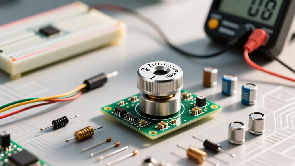
When makers and engineers first learn how to use potentiometer components, they typically grab the nearest 10kΩ rotary dial from a parts bin and wire it up. However, treating all potentiometers as identical is a critical prototyping error. The resistive track material—carbon composition, cermet, wirewound, or conductive plastic—dictates the component's noise floor, temperature coefficient, cycle life, and power handling. Choosing the wrong alternative leads to wiper noise in audio circuits, thermal drift in precision sensors, or catastrophic track burnout in power applications.
In this guide, we will compare the primary potentiometer alternatives, break down the electrical configurations required to use them effectively, and provide a decision matrix for your next PCB or breadboard project.
Track Material Alternatives: Carbon vs. Cermet vs. Wirewound
The physical makeup of the resistive element determines how the potentiometer behaves under electrical and mechanical stress. Here is how the main alternatives compare in real-world scenarios.
Carbon Composition: The Audio Standard and Its Limits
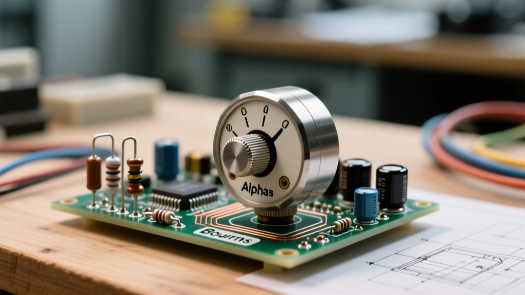
Carbon track potentiometers, such as the widely available Alpha RV16AF series, are manufactured by depositing a carbon-resin mixture onto a phenolic substrate. They are inexpensive and offer a wide range of tapers, including the logarithmic "A-taper" essential for human-hearing volume controls.
The Catch: Carbon tracks suffer from high Contact Resistance Variation (CRV). As the wiper moves, microscopic gaps in the carbon matrix cause resistance jumps, resulting in audible "scratch" noise in audio paths. Furthermore, carbon has a poor temperature coefficient (often ±500 ppm/°C), meaning the total resistance will drift significantly as the component heats up. They are strictly for low-power, user-facing adjustment where absolute precision is not required.
Cermet (Ceramic-Metal): High-Temp Precision Trimming
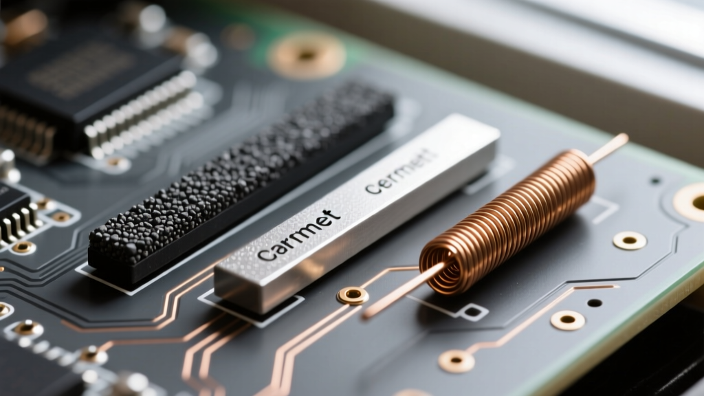
Cermet potentiometers fuse ceramic and metal alloys onto an alumina substrate, fired at high temperatures. The industry-standard Bourns 3296W 25-turn trimpot is a cermet device designed for through-hole calibration.
The Catch: Cermet is designed for "set-and-forget" calibration, not continuous user rotation. While it boasts an excellent temperature coefficient (±100 ppm/°C) and high power density, the brittle ceramic substrate can develop micro-cracks if subjected to continuous mechanical rotation or excessive physical torque on the adjustment screw. Use cermet alternatives for setting op-amp offsets or calibrating sensor baselines, but never as a user-facing volume knob.
Wirewound & Conductive Plastic: Niche but Critical Alternatives
Wirewound potentiometers (like the Vishay 534 series) consist of a resistive wire wound around a core. They excel in high-power applications (handling 2W to 5W+) and offer extreme linearity. However, the helical wire coil introduces parasitic inductance, making wirewound pots unsuitable for high-frequency RF or fast-switching PWM circuits. Additionally, the wiper "bounces" slightly as it transitions between wire loops, causing massive voltage spikes.
Conversely, conductive plastic potentiometers offer the smoothest wiper travel and lowest noise floor, making them the premium alternative for high-end studio audio faders and industrial joysticks, albeit at a 5x to 10x cost premium over carbon.
How to Use Potentiometer Configurations: Divider vs. Rheostat
Understanding the physical material is only half the battle. Knowing how to wire the three terminals dictates whether the component acts as a voltage reference or a current limiter.
Configuration A: The 3-Terminal Voltage Divider
This is the most common way to use a potentiometer for microcontroller inputs. By applying a reference voltage (e.g., 5V) across Pin 1 and Pin 3, the wiper (Pin 2) outputs a variable voltage proportional to its physical position. As detailed in SparkFun's Voltage Divider Tutorial, the output voltage is calculated as:
V_out = V_in × (R2 / (R1 + R2))
Crucial Microcontroller Insight: If you are feeding this wiper into an ADC (Analog-to-Digital Converter) like the ATmega328P on an Arduino Uno, you must respect the sample-and-hold capacitor's charging time. The ATmega328P datasheet mandates a source impedance of 10kΩ or less. If you use a 100kΩ potentiometer, the ADC will yield erratic, non-linear readings. The fix? Either use a 10kΩ pot, or solder a 100nF ceramic bypass capacitor directly between the wiper and ground to act as a local charge reservoir.
Configuration B: The 2-Terminal Variable Resistor (Rheostat)
By tying the wiper (Pin 2) to one of the outer pins (Pin 1 or Pin 3), the potentiometer becomes a two-terminal variable resistor. This configuration is used to limit current in real-time. While historically used for incandescent bulb dimming or motor speed control, using a potentiometer as a rheostat in modern DC power circuits is highly inefficient; the excess energy is burned off as heat directly inside the carbon track, leading to rapid thermal degradation. For modern power control, use a fixed resistor in series with a MOSFET driven by a PWM signal instead.
Comparative Matrix: Selecting the Right Component
Use this decision matrix to select the correct potentiometer alternative based on your specific project requirements.
| Track Material | Typical Model | Cycle Life | Temp Coefficient | Best Application |
|---|---|---|---|---|
| Carbon Comp. | Alpha RV16AF | 15,000 cycles | ±500 ppm/°C | User-facing audio volume, basic UI knobs |
| Cermet | Bourns 3296W | 200 cycles | ±100 ppm/°C | PCB calibration, op-amp offset trimming |
| Wirewound | Vishay 534 | 5,000 cycles | ±20 ppm/°C | High-power current limiting, heavy machinery |
| Conductive Plastic | BI Tech P160 | 50,000 cycles | ±250 ppm/°C | Studio audio faders, precision joysticks |
Real-World Failure Modes and Wiper Bounce Mitigation
Even when you select the correct alternative and wire it properly, environmental factors can degrade performance. The most common failure mode across all track types is wiper oxidation. Over time, humidity and airborne contaminants create a non-conductive film between the wiper contact and the resistive track. This manifests as "dead zones" where rotating the shaft yields no change in output voltage.
Mitigation Strategy: For sealed environments, specify IP-rated potentiometers. For existing circuits suffering from oxidation, a specialized contact cleaner (like DeoxIT) applied sparingly to the track can dissolve the oxide layer. Never use standard WD-40, as the petroleum distillates will dissolve the carbon-resin binder and permanently destroy the track.
Another critical issue is wiper bounce during rapid adjustment, particularly in wirewound and cheap carbon pots. If the wiper momentarily loses contact with the track in a voltage divider configuration, the microcontroller ADC pin is left "floating," which can result in wild voltage spikes that might trigger unintended logic states or reset the MCU. Always implement a software debounce algorithm (averaging 5-10 rapid ADC samples) or a hardware RC low-pass filter to smooth out these transient disconnects.
Final Prototyping Recommendations
Mastering how to use potentiometer alternatives requires matching the physical limitations of the track material to the electrical demands of your circuit. For breadboarding and basic Arduino inputs, a standard 10kΩ B-taper (linear) carbon pot is sufficient, provided you add a 100nF bypass capacitor at the wiper. For permanent PCB integration where calibration is required, invest in multi-turn cermet trimmers like the Bourns 3296 series to guarantee long-term thermal stability. Finally, reserve wirewound alternatives strictly for high-power, low-frequency analog applications, and always design your enclosures to protect the mechanical shaft from lateral stress.
For deeper insights into precision trimming and PCB layout considerations, refer to the Bourns Trimmer Design Guide, which provides extensive data on thermal profiles and soldering tolerances for cermet components.