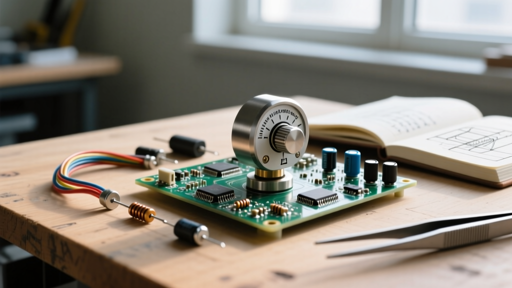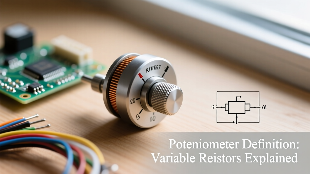

When you turn the volume knob on a guitar amplifier, adjust the brightness of a DIY LED array, or calibrate a sensor on a breadboard, you are interacting with one of the most fundamental components in electronics. But what exactly is the technical potentiometer definition? At its core, a potentiometer (colloquially known as a 'pot') is a three-terminal electromechanical device that acts as an adjustable voltage divider. By moving a wiper across a resistive track, you can manually control the electrical potential between two points, effectively giving you real-time, analog control over a circuit's behavior.
In this comprehensive how-it-works explainer, we will dissect the internal anatomy of potentiometers, explore the critical differences between wiring them as voltage dividers versus variable resistors, and provide actionable troubleshooting data for your prototyping bench.
The Anatomy of a Potentiometer: Wiper, Track, and Terminals
To truly understand how a pot functions, you must look inside the casing. Whether you are using a standard Alpha 16mm panel-mount pot or a precision Bourns 3386P cermet trimpot, the internal architecture relies on three main components:
- The Resistive Track: This is the physical material that provides the base resistance. Common materials include carbon composition (inexpensive, prone to noise), cermet (ceramic-metal composite, highly stable, used in trimmers), conductive plastic (smooth, high-resolution), and wirewound (high power, but low resolution due to wire coils).
- The Wiper: A spring-loaded metal contact that physically slides or rotates along the resistive track. The wiper is connected to the middle terminal (usually Pin 2) and acts as the output tap.
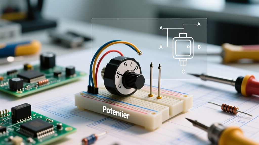
- The Terminals: A standard potentiometer features three pins. Pin 1 and Pin 3 are connected to the opposite ends of the resistive track. The total resistance between Pin 1 and Pin 3 is fixed and represents the nominal value of the pot (e.g., 10kΩ). Pin 2 is the wiper.
As the shaft rotates, the wiper changes the ratio of resistance between Pin 1 and Pin 2, and between Pin 2 and Pin 3. The sum of these two resistances always equals the total nominal resistance of the component.
Voltage Divider vs. Rheostat: The Two Wiring Modes
A common point of confusion for beginners is how to wire the three pins. The way you connect a potentiometer dictates its fundamental function in the circuit. According to the principles outlined by All About Circuits, there are two primary configurations:
Mode 1: The Voltage Divider (3-Terminal Configuration)
This is the truest application of the potentiometer definition. By applying a reference voltage (V_in) across Pin 1 and Pin 3, and reading the output from Pin 2 (the wiper), you create a voltage divider. The output voltage (V_out) is determined by the physical position of the wiper. The mathematical relationship is defined as:
V_out = V_in × (R2 / (R1 + R2))
Where R1 is the resistance between Pin 1 and the wiper, and R2 is the resistance between the wiper and Pin 3. This configuration is used for volume controls, sensor calibration, and generating analog reference voltages for microcontrollers.
Mode 2: The Rheostat (2-Terminal Configuration)
When you only use two pins—typically Pin 1 and Pin 2 (the wiper)—the potentiometer acts as a simple variable resistor, historically known as a rheostat. As you turn the knob, the total resistance in the circuit increases or decreases, which directly limits current flow. This mode is commonly used for LED dimming circuits, motor speed control, and tuning the gain of operational amplifiers. Pro Tip: Always connect the unused Pin 3 to the wiper (Pin 2) in a rheostat setup. If the wiper momentarily loses contact with the track due to vibration or dirt, the circuit will open entirely. Tying Pin 3 to the wiper ensures the circuit defaults to maximum resistance rather than breaking completely.
Understanding Tapers: Linear vs. Logarithmic Profiles
The 'taper' of a potentiometer defines how the resistance changes relative to the physical rotation of the shaft. Selecting the wrong taper is a frequent prototyping error that leads to poor user experiences, such as a volume knob that does nothing for 80% of its rotation and then suddenly blasts at maximum volume.
| Taper Type | Marking Code (Asia/EU) | Marking Code (US) | Resistance at Mid-Rotation (50%) | Primary Application |
|---|---|---|---|---|
| Linear | B | A | 50% of total resistance | Motor control, LED dimming, voltage dividers |
| Audio (Logarithmic) | A | C | ~10% to 15% of total resistance | Audio volume controls (matches human hearing) |
| Anti-Logarithmic | F | - | ~85% to 90% of total resistance | Synthesizer envelopes, specific balance controls |
Human hearing perceives loudness logarithmically, not linearly. Therefore, an 'Audio Taper' (Log) pot is designed so that the resistance changes slowly at the beginning of the rotation and rapidly at the end, creating a perceived linear increase in volume. If you are building an Arduino-based sensor array, you almost always want a Linear (B) taper to ensure predictable, proportional data mapping.
Interfacing Potentiometers with Microcontrollers (ADC Best Practices)
When translating the analog output of a potentiometer into digital data for an ESP32, Arduino, or STM32 microcontroller, you must wire the pot as a voltage divider (VCC to Pin 1, GND to Pin 3, Wiper to ADC pin). However, real-world implementation requires addressing electrical noise and impedance.
According to SparkFun's guide on voltage dividers, the resistance value of your pot matters immensely when dealing with Analog-to-Digital Converters (ADCs). A 10kΩ potentiometer is the gold standard for microcontroller prototyping. Why? Microcontroller ADCs use an internal sample-and-hold capacitor that must charge up to the input voltage during the sampling window. If you use a 1MΩ potentiometer, the high source impedance prevents the capacitor from charging fast enough, resulting in wildly inaccurate, fluctuating readings. Conversely, a 100Ω pot will draw excessive current (up to 50mA at 5V), wasting battery life and generating excess heat.
The Hardware Filter Fix: Even with a 10kΩ pot, long wires can act as antennas, picking up electromagnetic interference (EMI) and causing 'jitter' in your ADC readings. To solve this, solder a 100nF (0.1µF) ceramic capacitor directly between the wiper pin and ground. This creates a simple RC low-pass filter that smooths out high-frequency noise, giving your microcontroller a rock-solid analog reading.
Real-World Failure Modes and Troubleshooting
Potentiometers are mechanical components, meaning they are subject to physical wear and environmental degradation. Recognizing these failure modes will save you hours of debugging on the bench:
- 'Scratchy' Audio Noise: In carbon-track pots, dust, oxidation, and carbon wear can create dead spots on the track. When the wiper passes over these spots, it causes rapid resistance spikes, heard as crackling in audio circuits. Solution: Spray a specialized contact cleaner like DeoxIT D5 into the casing slot and rotate the shaft 50 times to clean the track. Do not use standard WD-40, as it leaves a conductive, dust-attracting residue.
- Wiper Bounce in Wirewound Pots: Wirewound potentiometers are constructed by wrapping nichrome wire around a core. As the wiper slides over the individual coils, it can momentarily bounce or bridge two coils simultaneously. In precision DC circuits, this causes micro-voltage spikes. Solution: Avoid wirewound pots for precision DC voltage dividers; opt for conductive plastic or cermet instead.
- Mechanical Looseness: Over time, the crimped metal casing holding the pot together can loosen, causing the internal wiper to lose spring tension against the track. This manifests as intermittent signal loss. Solution: Gently squeeze the metal retention tabs with needle-nose pliers to restore wiper pressure, or replace the component if it is a cheap carbon-composition unit.
Summary: Choosing the Right Component
Understanding the potentiometer definition goes far beyond memorizing a textbook phrase; it requires a practical grasp of materials, circuit topologies, and microcontroller interfacing. Whether you are selecting a precision multi-turn cermet trimpot to calibrate a medical sensor, or wiring a rugged 100kΩ linear panel pot to control a PWM motor driver, matching the component's physical taper, resistance, and material to your specific electrical requirements is the hallmark of successful electronics design. Always verify your taper codes, respect ADC impedance limits, and filter your wiper outputs to ensure your DIY projects perform flawlessly in the real world.