To find the equivalent resistance of multiple components sharing the same two electrical nodes, you use the reciprocal sum formula. When you input values into a total resistance in a parallel circuit calculator, the tool computes this exact relationship: the inverse of the sum of the inverses of each branch. For two resistors, this simplifies to the 'product over sum' method. But knowing the math is only the first step; applying it to select real-world, off-the-shelf components that survive thermal and fault conditions is where actual circuit design begins.
The Core Topology: Nodes, Branches, and the Inverse Sum
A parallel resistor network is defined by its topology: every resistor connects between the exact same two electrical nodes. Let us label the top common connection Node A and the bottom common connection Node B. Because all components bridge Node A and Node B, the voltage drop across every single branch is identical, regardless of the individual resistance values.
The governing equation for n resistors is:
R_total = 1 / ( (1/R1) + (1/R2) + ... + (1/Rn) )
For exactly two resistors, the calculator uses the simplified product-over-sum formula: R_total = (R1 × R2) / (R1 + R2). A fundamental rule of this topology is that the total equivalent resistance will always be lower than the smallest individual resistor in the network.
If you need a 50Ω resistance capable of dissipating 2W, you could use a single 50Ω 2W resistor. However, 2W axial resistors are physically large and run hot. By placing two 100Ω 1W resistors in parallel, you achieve the same 50Ω total resistance. The current splits evenly, each resistor dissipates only 1W, and the combined surface area dissipates heat much more efficiently, keeping the PCB temperature down. Furthermore, if one fails open, the circuit continues to function at 100Ω rather than breaking entirely.
Behavior Matrix: What Happens When Elements Change or Fail
Understanding failure modes is critical. Unlike series circuits where an open component kills the entire current path, parallel circuits behave differently under fault conditions. Below is the behavior matrix assuming an ideal constant-voltage source driving Node A to Node B.
| Event / Fault | Effect on Total Resistance | Effect on Total Current | Effect on Remaining Branches | System Outcome & Thermal Risk |
|---|---|---|---|---|
| Add a Resistor | Decreases | Increases | Unchanged (ideal source) | Higher total power draw; ensure source can handle the extra current. |
| Remove a Resistor (Open) | Increases | Decreases | Unchanged (ideal source) | Safe. Circuit continues operating at a higher total resistance. |
| Short One Resistor | Drops to ~0Ω | Spikes to Maximum | Current drops to ~0A in parallel branches | Catastrophic. Source current limits or wiring melts. The shorted path absorbs all energy. |
| One Resistor Drifts High (Heat) | Increases slightly | Decreases slightly | Current shifts to the cooler branches | Self-balancing. The cooler resistors take on more current, which is generally stable. |
The critical contrast here is the short circuit. In a series string, shorting one resistor simply bypasses it, lowering total resistance but usually keeping current within safe bounds. In a parallel network, shorting one branch creates a direct short across Node A and Node B, effectively shorting the power supply and bypassing all other parallel branches. Always fuse the main feed to a parallel network.
Design Walkthrough: Hitting 47.5Ω at 1.5W Using Standard Values
Let us use the conceptual framework of a total resistance in a parallel circuit calculator to solve a real bench problem. You are designing a dummy load for an RF transmitter and need exactly 47.5Ω. The load will dissipate 1.5W continuously. You only have standard E24 series (5%) or E96 series (1%) resistors in your kit.
Step 1: Pick a base resistor.
Let us choose R1 = 100Ω (a very common E24 value). We need to find R2.
Step 2: Rearrange the product-over-sum formula to solve for R2.
R2 = (R1 × R_target) / (R1 - R_target)
R2 = (100 × 47.5) / (100 - 47.5)
R2 = 4750 / 52.5 = 90.47Ω
Step 3: Select the nearest standard value.
The closest E24 value to 90.47Ω is 91Ω. Let us plug 100Ω and 91Ω back into the calculator to verify:
R_total = (100 × 91) / (100 + 91) = 9100 / 191 = 47.64Ω.
This is a 0.3% error from our 47.5Ω target, which is well within the tolerance of standard components.
Step 4: Calculate Power Dissipation per Branch.
Assume a constant 8.45V across the network (which yields ~1.5W total).
Power in R1 (100Ω): P = V² / R = (8.45²) / 100 = 0.71W
Power in R2 (91Ω): P = V² / R = (8.45²) / 91 = 0.78W
Step 5: Component Selection.
Both resistors will dissipate under 0.8W. A standard 1/4W (0.25W) resistor will instantly overheat and fail. You must select 1W resistors. I recommend the Vishay PR01 series 1W metal film resistors. They are flameproof, handle surges well, and cost roughly $0.15 each in small quantities. Select the PR01000101009JA100 (100Ω) and PR01000109109JA100 (91Ω).
Breadboard Testing: Step-by-Step Verification
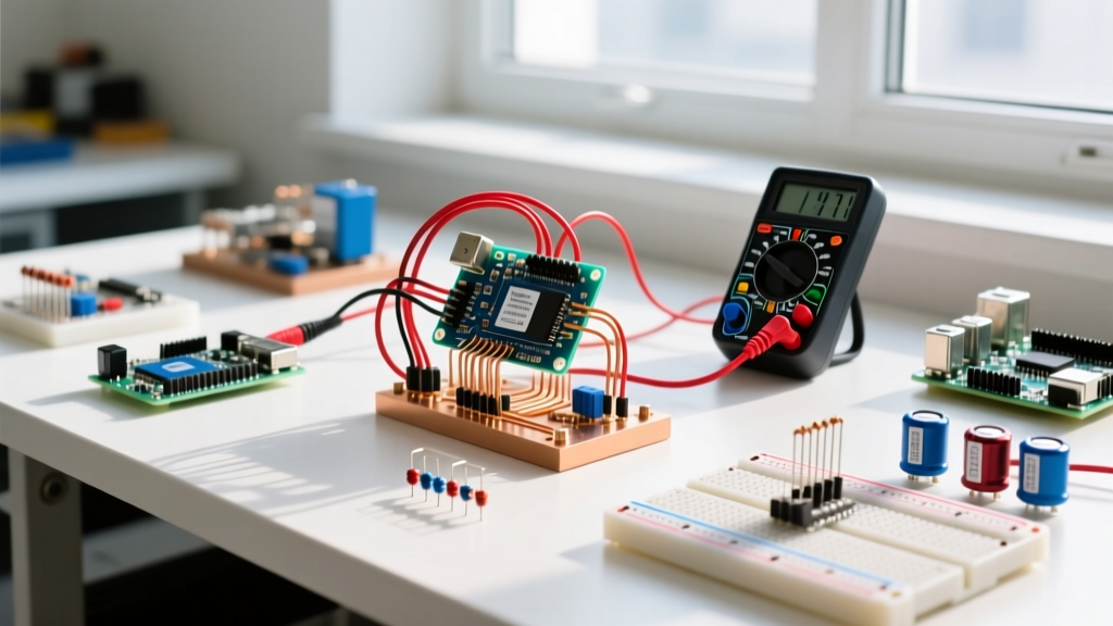
Before soldering your custom parallel network into a permanent PCB, verify it on a breadboard. Breadboards introduce parasitic contact resistance, which can skew low-resistance measurements.
- De-energize the Circuit: Ensure no power is applied to the breadboard. Measuring resistance on a live circuit will yield false readings and can blow the internal fuse of your digital multimeter (DMM).
- Null Your DMM Leads: Touch the red and black probes together. Note the residual resistance of your test leads (usually 0.2Ω to 0.4Ω). You will subtract this from your final reading.
- Measure Individual Branches: Insert R1 (100Ω) and R2 (91Ω) into separate, unconnected rows. Measure each to confirm they are within their 1% or 5% tolerance band before wiring them together.
- Wire the Parallel Nodes: Use solid 22 AWG jumper wires to connect the top leads of both resistors to a single continuous power rail (Node A). Connect the bottom leads to a different continuous ground rail (Node B).
- Measure the Network: Place your DMM probes directly on the metal leads of the resistors where they enter the breadboard, not on the distant power rails. This eliminates the breadboard's internal rail resistance from your measurement.
- Verify the Math: Your DMM should read approximately 48.0Ω (47.64Ω theoretical + ~0.3Ω breadboard contact resistance). If it reads significantly higher, check for a loose jumper wire causing an open branch.
Decision Tree: Selecting Your Parallel Resistor Strategy
Not every design requires a parallel network. Use this decision matrix to determine if a parallel configuration is the correct engineering choice for your specific constraints.
| Design Constraint | If True... | Then Choose... |
|---|---|---|
| Requires ultra-high precision (< 0.1% tolerance) | Parallel networks compound tolerance errors and thermal drift. | A single precision resistor (e.g., Susumu RG series 0.1%). |
| Operating voltage exceeds 250V | Parallel resistors share current, but a single open fault places full voltage on the survivor. | A series resistor string to divide voltage stress safely. |
| Total power dissipation > 0.5W, standard values only | Single high-wattage resistors are expensive and thermally dense. | Parallel network of two or more 1W standard resistors. |
| Need a non-standard odd value (e.g., 31.4Ω) quickly | Waiting for custom mail-order parts delays prototyping. | Parallel network calculated via the inverse-sum method using E24 parts on hand. |
Final Recommendation: The 2-Resistor E24 Default
For 90% of hobbyist, prototyping, and general-purpose power-resistance needs where a specific odd value or higher wattage is required, default to a two-resistor parallel network using 1% tolerance E24 metal film resistors. Specifically, stock the Yageo MFR-25 series (1/4W) for signal-level dummy loads and the Vishay PR01 series (1W) for power applications.
Using a total resistance in a parallel circuit calculator to pair a 100Ω and a 91Ω resistor gives you a highly stable, thermally balanced 47.6Ω network that outperforms a single 2W wirewound resistor in both thermal management and high-frequency parasitic inductance. Always fuse the main supply node to protect against the catastrophic short-circuit failure mode inherent to parallel topologies, and verify your physical build by subtracting DMM lead resistance from your breadboard measurements.