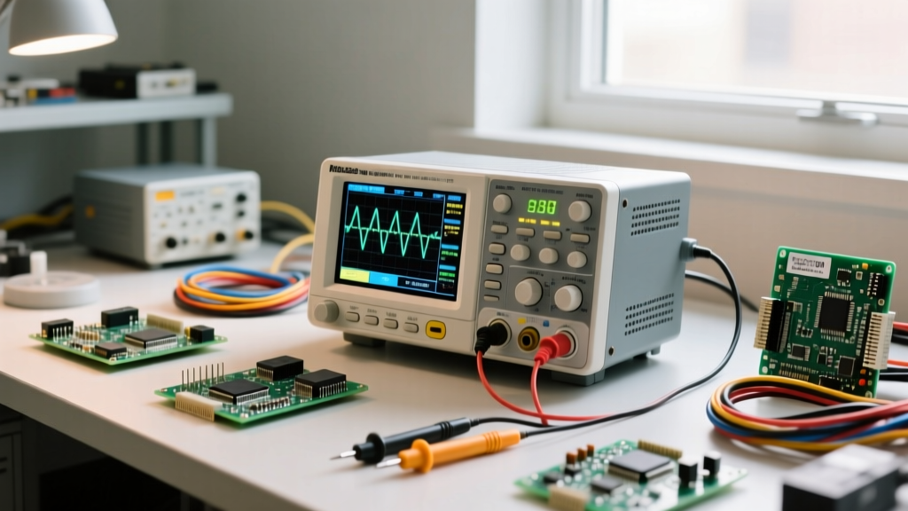

The direct answer to diagnosing mixed-signal circuits is that you must master three specific oscilloscope functions: edge triggering with holdoff, AC/DC coupling toggling, and FFT (Fast Fourier Transform) math. While a multimeter gives you an averaged DC value, an oscilloscope reveals the transient reality of your circuit. If your 5V buck converter rail reads 4.9V on a multimeter but is actually oscillating between 4.2V and 5.6V at 500kHz, your microcontroller will brownout. Understanding how to configure your scope to capture these hidden anomalies is the difference to a working prototype and a mysterious field failure.
This guide assumes we are diagnosing a standard 12V-to-5V synchronous buck converter switching at 500kHz. We will cover the exact setup, safety requirements for mains-adjacent measurements, and a concrete decision tree to isolate faults.
Core Oscilloscope Setup for PWM and Ripple Capture
Before touching the probe to the board, you must configure the front panel. Treating an oscilloscope like a plug-and-play voltmeter guarantees aliased or misleading waveforms. Use the following setup block as your baseline for switching power supply diagnostics.
Scope Setup Block: Buck Converter Diagnostics
- Probe Attenuation: 10X (physically switch the probe to 10X and verify the scope channel menu matches). 1X limits bandwidth to ~10MHz, hiding high-frequency ringing.
- Channel 1 (Switch Node / PWM): DC Coupling, 5V/div vertical scale, 2µs/div timebase. DC coupling is mandatory here to see the true duty cycle relative to 0V.
- Channel 2 (Output Ripple): AC Coupling, 20mV/div vertical scale, 1ms/div timebase. AC coupling blocks the 5V DC offset, allowing you to zoom in on the millivolt-level AC ripple.
- Trigger Function: Edge trigger, rising slope. Set the trigger level to 50% of the expected PWM amplitude (e.g., 6V for a 12V gate drive). Enable Trigger Holdoff at 1.5µs to prevent false triggering on switch-node ringing.
- Bandwidth Limit: Engage the 20MHz hardware filter on Channel 2 to eliminate high-frequency radiated noise from the switching node, isolating the actual output capacitor ripple.
Probe Placement and Safety Categories for Mains Circuits
When measuring the secondary (output) side of an isolated power supply, standard passive probes referenced to earth ground are safe. However, if you are probing the primary side (e.g., the high-voltage switching node of an offline flyback converter connected directly to rectified 120V/240V AC), standard probes become lethal hazards.
A common, highly dangerous mistake is using an isolation transformer to power the oscilloscope itself so the probe ground clip can be attached to a live mains voltage. This turns the entire metal chassis of the scope into a lethal shock hazard. According to IEC 61010-1 safety standards, measuring primary-side mains circuits requires a dedicated CAT II 1000V or CAT III 600V differential probe (such as the Micsig DP10013 or Tektronix THDP0200). Always keep the oscilloscope grounded via its 3-prong mains cord.
Probe Placement Technique: For the switch node (Channel 1), place the probe tip directly on the MOSFET drain or inductor pad. Crucially, remove the standard alligator ground clip and use the probe’s ground spring. The alligator clip creates a 2-inch loop antenna that will pick up magnetic flux from the inductor, showing 10V of "ringing" that doesn't actually exist on the board. The ground spring reduces this loop to millimeters, yielding an accurate waveform.
Expected Readings: Good vs. Bad Signatures
Once your oscilloscope functions are dialed in, you need to know what the data actually means. The table below provides the numeric thresholds for a healthy 500kHz buck converter versus one suffering from component degradation or layout faults.
| Measurement Target | Scope Function Used | Good Reading (Numeric) | Bad Reading & Probable Cause |
|---|---|---|---|
| Switch Node Rise Time | DC Coupling, 2ns/div | < 15ns (clean edge) | > 40ns (Gate resistor too high or weak driver) |
| Switch Node Ringing | DC Coupling, Cursor peak-to-peak | < 20% of Vin (e.g., < 2.4V on 12V rail) | > 50% of Vin (Excessive parasitic inductance, needs RC snubber) |
| Output Ripple (Switching Freq) | AC Coupling, 20MHz BW Limit | < 30mV p-p at 500kHz | > 80mV p-p (Output ceramic capacitor ESR degraded or missing) |
| Output Ripple (Line Freq) | AC Coupling, FFT Math Function | No 120Hz spike visible | Distinct 120Hz spike (Bulk input electrolytic capacitor dried out) |
Common Mistakes That Yield Misleading Waveforms
Even with a $2,000 oscilloscope, user error will generate phantom faults. Watch out for these three specific mistakes:
- The 1X/10X Software Mismatch: If your physical probe is set to 10X, but the scope channel menu is accidentally set to 1X, the scope will display a 5V signal as 0.5V. You will mistakenly think your power rail has collapsed. Always verify the software attenuation matches the physical probe switch before taking measurements.
- AC Coupling on the Switch Node: If you accidentally leave Channel 1 in AC coupling while measuring the PWM gate drive, the scope removes the DC offset. A 0V-to-12V PWM signal will be displayed as a -6V to +6V signal. This distorts your duty cycle calculations and makes it impossible to verify if the gate is actually reaching the required 10V+ threshold to fully enhance the MOSFET.
- Aliasing from Slow Timebases: If you are looking for 500kHz ripple but your timebase is set to 10ms/div, the scope's sample rate drops dramatically. The 500kHz signal will alias, appearing as a random, low-frequency sine wave. Always ensure your timebase is fast enough to satisfy the Nyquist criterion for your target frequency (at least 50µs/div for 500kHz).
Decision Tree: Isolating the Fault in a Failing Buck Converter
Use this if-then decision path when your DC output is out of regulation or exhibiting excessive noise. This terminates in a concrete component-level fix.
Diagnostic Decision Path
- IF the output voltage is low (e.g., 4.2V instead of 5V) AND the PWM duty cycle on the switch node is maxed out (>95%):
→ The feedback loop is broken. Check the feedback (FB) resistor divider with a multimeter. If resistors are nominal, the FB pin trace is likely cracked. Action: Solder a jumper wire from the FB pin directly to the resistor divider node. - IF the output voltage is correct (5.0V) AND the PWM duty cycle is normal (~42%) AND Channel 2 (AC coupled) shows >100mV of high-frequency ripple:
→ The output filtering is insufficient. Check if the ripple frequency matches the 500kHz switching frequency. If yes, the ceramic output capacitors have lost capacitance due to DC bias derating or micro-cracking. Action: Parallel two additional 22µF 10V X7R MLCCs (e.g., Murata GRM21BR71A226ME51) directly across the output terminals. - IF the output voltage is correct AND the FFT math function shows a massive fundamental spike at exactly 120Hz (or 100Hz in 50Hz regions):
→ The primary-side bulk storage is failing. The input electrolytic capacitor has dried out and can no longer smooth the rectified mains ripple, which is coupling through the transformer/inductor. Action: Replace the primary bulk capacitor with a low-ESR, high-temperature polymer or electrolytic capacitor. Concrete Pick: Install a Panasonic OS-CON 100µF 35V polymer capacitor (Part: 35SEPC100M) which offers an ESR of just 14mΩ and a 5000-hour lifespan at 105°C.
Recommended Scope and Probe Configurations for Bench Builds
For hobbyists and junior engineers building a diagnostic bench in 2026, you do not need a $15,000 Tektronix MSO6 to perform these measurements. The Analog Devices guidelines on ripple measurement emphasize technique over raw scope price.
A 4-channel, 200MHz scope like the Siglent SDS1204X-E (typically around $450) or the Rigol MSO5074 (around $900) provides more than enough bandwidth and sample rate (1 GSa/s) to accurately capture 500kHz switch-node ringing and nanosecond rise times. Pair it with a high-quality passive probe (like the Siglent PP350) for secondary-side measurements, and invest in a Micsig DP10013 differential probe (approx. $130) for any primary-side mains measurements. This combination gives you 12-bit equivalent resolution through averaging, robust FFT math functions, and the safety margins required to debug real-world power electronics without risking your equipment or your life.


