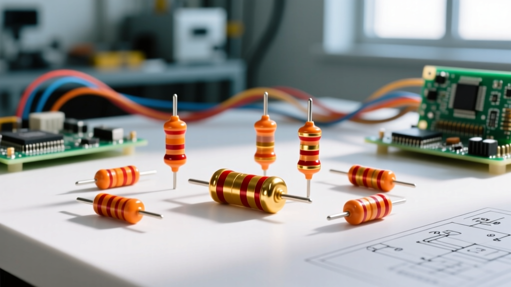

An orange-orange-red-gold resistor is a 3.3 kΩ (3,300 ohms) component with a ±5% tolerance. It is one of the most common values in the E24 standard series, serving as a workhorse for I2C pull-ups, LED current limiting, and transistor base biasing. If you are holding one in your hand right now, you are looking at a part that will pass roughly 1 mA of current when dropped across a standard 3.3V logic rail.
Below is a complete bench-level breakdown of how to read this specific part, which construction material to select for your circuit, how these components fail in the wild, and how to safely substitute when your parts bin runs dry.
Decoding the Bands: What Orange-Orange-Red-Gold Means
Through-hole resistors use a standardized color code defined by IEC 60062. For a 4-band resistor, the first two bands represent the significant digits, the third is the multiplier, and the fourth is the tolerance. Here is the exact mathematical breakdown for the orange-orange-red-gold sequence:
- Band 1 (Orange): First significant digit = 3
- Band 2 (Orange): Second significant digit = 3
- Band 3 (Red): Multiplier = 10² (or 100)
- Band 4 (Gold): Tolerance = ±5%
The Math: 33 × 100 = 3,300 Ω, which is universally written as 3.3 kΩ.
Resistor Construction Types: Which 3.3kΩ to Choose
Not all 3.3 kΩ resistors are built the same. The internal construction dictates the parasitic inductance, thermal noise, and long-term stability. Use this comparison matrix to select the right physical part for your specific application.
| Type | Construction | Tolerance | Tempco (ppm/°C) | Typical Use Case |
|---|---|---|---|---|
| Carbon Film | Carbon coating on ceramic former | ±2% to ±5% | -200 to -800 | General hobbyist projects, non-critical LED limiting. |
| Metal Film | NiCr (Nichrome) sputtered on ceramic | ±0.1% to ±1% | ±50 to ±100 | Precision analog, audio signal paths, sensor dividers. |
| Thick Film (SMD) | Ruthenium oxide paste fired on alumina | ±1% to ±5% | ±100 to ±200 | High-density PCBs, microcontroller breakouts. |
| Carbon Comp | Clay and carbon dust compressed mix | ±5% to ±20% | High (>1000) | Vintage audio restoration, high-energy pulse absorption. |
| Wirewound | Nichrome wire wound on fiberglass core | ±1% to ±5% | ±20 to ±50 | High-power dissipation (rarely needed for 3.3kΩ). |
Selection Rule of Thumb: For 90% of DIY and prototyping tasks (like pulling up an I2C line or biasing a 2N2222 transistor), a standard 1/4W carbon film or metal film axial resistor (such as the Yageo CFR-25 or Vishay MFR-25 series) is the correct choice. Reserve metal film for ADC voltage dividers where thermal drift will ruin your measurement accuracy.
Real-World Applications for 3.3kΩ Resistors
The 3.3 kΩ value is a staple in the E24 series because it perfectly bridges the gap between low-power signal routing and adequate current sinking. Here is where you will see it on the bench:
1. I2C Bus Pull-Up Resistors (3.3V Logic)
When designing an I2C bus on a 3.3V microcontroller (like an ESP32 or STM32), the bus requires pull-up resistors on the SDA and SCL lines. While 4.7 kΩ is standard for 100 kHz (Standard Mode), a 3.3 kΩ resistor is the optimal choice for 400 kHz (Fast Mode). According to the NXP I2C-bus specification (UM10204), a lower resistance value pulls the line high faster against the parasitic capacitance of the PCB traces, ensuring clean rise times without exceeding the 3 mA maximum sink current of most I/O pins.
2. Low-Current LED Indicators
Modern high-efficiency LEDs (like the Lite-On LTL-307E) are painfully bright at 20 mA. For a power indicator on a 5V rail, you want a subtle glow that draws minimal current. Assuming a forward voltage (Vf) of 2.0V for a standard red LED:
I = (V_source - Vf) / R = (5V - 2.0V) / 3300Ω = 0.9 mA
This yields roughly 1 mA of current—enough to clearly illuminate a high-efficiency LED without wasting battery life in a portable device.
3. Transistor Base Biasing
When driving a standard NPN transistor (e.g., 2N3904) from a 3.3V GPIO pin to switch a 12V relay, you need to limit the base current. A 3.3 kΩ resistor between the GPIO and the base limits the current to roughly 0.8 mA. Assuming a conservative Beta (hFE) of 100, this provides up to 80 mA of collector current, which is more than enough to saturate the transistor for small relay coils or indicator loads.
Failure Modes and Visual Symptoms
Resistors are generally the most reliable components on a board, but they do fail when subjected to environmental or electrical abuse. Here is how to diagnose a failed 3.3 kΩ part based on visual and electrical symptoms.
- Thermal Overload (Open Circuit): If a 1/4W resistor is forced to dissipate 1W, it will overheat. Visual symptom: The epoxy coating will blister, turn dark brown or black, and emit a distinct acrid, burnt-sugar smell. The resistance will often measure as an infinite open circuit on a multimeter.
- Moisture Ingress (Resistance Drift High): Carbon film resistors are slightly porous. In high-humidity environments without conformal coating, moisture penetrates the epoxy. Visual symptom: None. The part looks pristine, but the resistance will slowly drift upward (e.g., reading 3.8 kΩ or higher) over months of operation.
- Mechanical Fracture (SMD Intermittent Open): Thick-film SMD resistors (like 0603 or 0805 packages) are brittle. If the PCB flexes during installation or thermal cycling, the ceramic body cracks. Visual symptom: A microscopic hairline crack across the ceramic body, visible only under 10x magnification. The circuit will work when cold, but fail when the board heats up and expands.
Safe Substitution Rules When You're Out of 3.3kΩ Parts
If your bench stock of 3.3 kΩ resistors is empty, you can safely synthesize the value using series or parallel combinations. The key is to maintain the required power rating and tolerance.
- Series Combination (Addition): Place a 1.5 kΩ and a 1.8 kΩ resistor in series. (1500 + 1800 = 3300 Ω). Advantage: The power handling capability doubles. Two 1/4W resistors in series can safely dissipate 1/2W total.
- Parallel Combination (Product over Sum): Place two 6.8 kΩ resistors in parallel. (6800 / 2 = 3400 Ω). While 3.4 kΩ is not exactly 3.3 kΩ, it is only a 3% deviation. For I2C pull-ups or LED limiting, a 3% deviation is entirely negligible and functionally identical.
- Trimpot Substitution: For prototyping, use a 5 kΩ Bourns 3296W multi-turn trimpot. Set it to 3.3 kΩ using your multimeter. Caution: Trimpots have poor temperature coefficients and are prone to vibration-induced wiper movement. Never use a trimpot as a permanent substitute in a production environment.
Frequently Asked Questions
What is the exact wattage rating of a standard orange-orange-red-gold resistor?
The color bands only dictate resistance and tolerance, not wattage. However, the physical size of an axial through-hole resistor dictates its power rating. A standard orange-orange-red-gold resistor measuring roughly 6.3mm in length and 2.3mm in diameter is rated for 1/4 Watt (0.25W). If the part is smaller (approx. 3.6mm long), it is a 1/8W (0.125W) variant. Always verify the physical footprint against the manufacturer datasheet if operating near the thermal limit.
Can I use a 3.3kΩ 5% carbon film resistor instead of a 1% metal film part?
Yes, for digital logic (pull-ups/pull-downs), LED current limiting, and basic transistor biasing. The 5% tolerance and higher thermal noise of carbon film will not affect these applications. However, do not substitute if the 3.3 kΩ resistor is part of a precision voltage divider feeding an ADC, or if it is in the feedback loop of an op-amp. In those analog signal paths, the 5% initial error and the -500 ppm/°C temperature drift will introduce unacceptable measurement inaccuracies.
Why does my multimeter read 3.38kΩ on a brand-new orange-orange-red-gold resistor?
This is normal and within specification. The gold band indicates a ±5% manufacturing tolerance. 5% of 3,300 Ω is 165 Ω. Therefore, the acceptable factory range is 3,135 Ω to 3,465 Ω. A reading of 3.38 kΩ (3,380 Ω) sits comfortably inside this window. Additionally, ensure your multimeter's test leads are shorted and zeroed; cheap test leads can introduce 0.2 Ω to 0.5 Ω of series resistance, though this is negligible at the kilo-ohm scale.
How do I read the SMD code equivalent for an orange-orange-red-gold resistor?
If you are transitioning from through-hole to surface mount, the 3.3 kΩ value is marked differently depending on the tolerance of the SMD part. For a standard 5% tolerance SMD resistor (E24 series), the 3-digit code is 332 (33 × 10²). For a 1% tolerance precision SMD resistor (E96 series), the 4-digit code is 3302 (330 × 10²). Both serve the exact same electrical function as the axial orange-orange-red-gold part.


