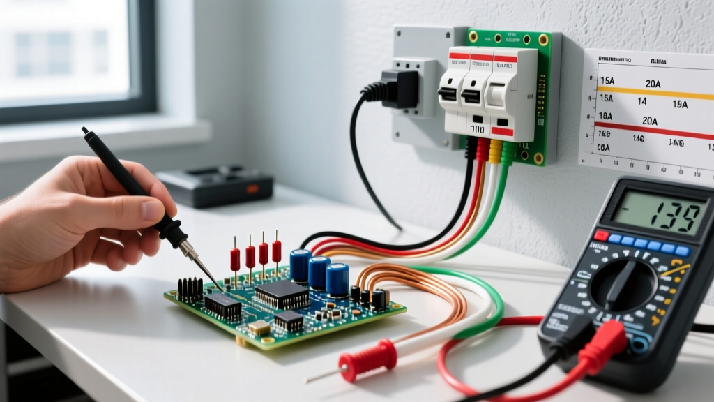
Ohm's Law is the foundational electrical principle stating that the current flowing through a linear conductor is directly proportional to the voltage applied across it and inversely proportional to its resistance. When you apply this to a workbench or jobsite, it stops being abstract algebra and becomes the primary tool for preventing melted wires, undersized components, and mysterious voltage drops.
The Core Formula and Quick-Reference Table
At its core, the relationship is defined by V = I × R. According to All About Circuits, this linear relationship holds true for most standard conductors and resistors at stable temperatures. Below is the quick-reference matrix you need when troubleshooting or designing a circuit. Keep this table in mind before reaching for an online calculator.
| To Find | Formula | Variables | Real-World Bench Example |
|---|---|---|---|
| Voltage (V) | V = I × R |
I = Current (Amps), R = Resistance (Ohms) | 2A flowing through a 4Ω power resistor yields an 8V drop across it. |
| Current (I) | I = V / R |
V = Voltage (Volts), R = Resistance (Ohms) | 120V applied across a 24Ω space heater element draws exactly 5A. |
| Resistance (R) | R = V / I |
V = Voltage (Volts), I = Current (Amps) | A 12V DC motor drawing 3A under load has an effective resistance of 4Ω. |
| Power (P) | P = V × I |
V = Voltage (Volts), I = Current (Amps) | A 120V branch circuit pulling 15A delivers 1800W (Watt's Law extension). |
Worked Example: Sizing Wire for a 12V LED Strip
Theory is useless if it doesn't tell you what to buy. Let's use Ohm's Law to size the feeder wire for a high-draw 12V WS2815 addressable LED strip. This is a scenario where ignoring the math results in severe color shifting at the far end of the strip due to voltage drop.
The Setup:
- Load: 5-meter WS2815 strip (60 LEDs/m).
- Max Current (I): 15A (calculated from 15mA per channel × 3 channels × 300 LEDs, plus a safety margin).
- Power Supply: 12V DC, located 3 meters away from the strip's start.
- Acceptable Voltage Drop (V): 0.5V maximum (to keep the strip above 11.5V).
The Calculation:
First, we find the maximum allowable resistance for the entire wire run using the resistance formula: R = V / I.
R = 0.5V / 15A = 0.033Ω
This 0.033Ω is the maximum resistance allowed for the entire loop. Since the power supply is 3 meters away, we need a positive wire (3m) and a negative wire (3m), making the total wire length 6 meters.
Next, we find the maximum resistance per meter:
0.033Ω / 6m = 0.0055Ω per meter
The Decision:
Looking at standard copper wire tables at 20°C, 14 AWG wire has a resistance of roughly 0.0082Ω/m. That is too high; it will cause a voltage drop of nearly 0.75V, starving the end of the strip. However, 12 AWG wire has a resistance of approximately 0.0052Ω/m. This falls safely under our 0.0055Ω/m threshold. Ohm's Law just dictated that you must buy 12 AWG wire, not the cheaper 14 AWG, to maintain signal integrity.
Where You Meet This in Practice (and What It Changes)
You rarely sit down with a calculator on the jobsite, but Ohm's Law dictates the physical behavior of every installation you touch. Here is where it manifests and what it changes in a real circuit:
1. Corroded Terminals and Loose Connections
When a terminal block corrodes or a wire nut is left loose, you are inadvertently introducing a high-resistance component in series with your load. According to V = I × R, as that contact resistance (R) increases, the voltage dropped across that bad connection increases. What it changes: The voltage actually reaching the load drops, causing motors to run hot and lights to dim, while the corroded terminal dissipates the lost voltage as heat, eventually melting the insulation.
2. Short Circuits and Breaker Trips
A short circuit occurs when current bypasses the load, creating a path where resistance (R) approaches zero. If R is 0.01Ω on a 120V line, I = 120V / 0.01Ω = 12,000A. What it changes: This massive, instantaneous spike in current generates extreme magnetic and thermal forces, which is exactly what the thermal-magnetic trip mechanism inside your circuit breaker is designed to detect and interrupt within milliseconds.
3. Current-Limiting Resistors
If you are wiring a 2V, 20mA indicator LED to a 12V DC bus, you cannot connect it directly. You must drop the remaining 10V across a resistor. Using R = V / I, you calculate 10V / 0.02A = 500Ω. You would select the next standard E12 value, which is 510Ω.
Common Confusions: Ohm's Law vs. Watt's Law
The most frequent mistake hobbyists and junior technicians make is conflating Ohm's Law with Watt's Law (sometimes called Joule's Law in this context).
- Ohm's Law (
V = I × R) defines the relationship between voltage, current, and resistance. It tells you how a material opposes electron flow. - Watt's Law (
P = V × I) defines the relationship between voltage, current, and power. It tells you how much work is being done or heat is being generated.
Why the confusion matters: If you use Ohm's Law to calculate that you need a 100Ω resistor to limit current to an LED, you have only done half the job. You must then use Watt's Law (P = I² × R or P = V × I) to calculate how much heat that resistor will dissipate. If the math shows it will dissipate 0.8W, and you install a standard 0.25W (1/4W) through-hole resistor, it will overheat, char the PCB, and fail open. You need Ohm's Law to find the part value, and Watt's Law to find the part's physical size and wattage rating.
FAQ: Troubleshooting and Edge Cases
Does Ohm's Law apply to AC circuits and household wiring?
Yes, but with a critical modification. In Alternating Current (AC) circuits containing capacitors or inductors (like motors and transformers), simple resistance (R) is replaced by impedance (Z). Impedance factors in reactance, which varies with frequency. The formula becomes V = I × Z. For purely resistive AC loads, like baseboard heaters or incandescent bulbs, standard Ohm's Law applies perfectly using RMS voltage and current values. For deeper reading on AC impedance, HyperPhysics at Georgia State University provides excellent vector diagrams.
Why doesn't my multimeter read exactly the calculated current when I test an LED?
Because LEDs and diodes are non-ohmic devices. Ohm's Law assumes a linear relationship where resistance is constant regardless of voltage. A diode's resistance changes drastically depending on the forward voltage applied. Once the LED hits its forward voltage threshold (e.g., 2.1V for red), its resistance drops exponentially, and current spikes. This is exactly why you must use a current-limiting resistor or a constant-current driver in series with them.
If I double the voltage, does the current always double?
Only if the resistance remains perfectly constant. In the real world, as current increases, components heat up. For materials like tungsten (in incandescent bulbs) or copper wire, resistance increases as temperature rises. Therefore, doubling the voltage will result in slightly less than double the steady-state current because the hotter filament or wire presents higher resistance.