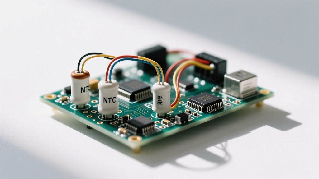

An NTC (Negative Temperature Coefficient) thermistor for inrush current limiting is a temperature-dependent resistor placed in series with a power supply's AC input that presents high resistance at cold startup to choke off surge currents, then self-heats and drops to near-zero resistance during steady-state operation. By dynamically altering its impedance, it fundamentally changes the transient startup profile of a power circuit, preventing upstream branch breakers from nuisance-tripping and protecting downstream bridge rectifiers and bulk filter capacitors from catastrophic overcurrent failure. If you are designing or repairing switch-mode power supplies (SMPS), audio amplifiers, or motor drives, understanding how to size and place these components is non-negotiable for reliability.
The Core Mechanism: How NTCs Change the Circuit
NTC inrush limiters are typically manufactured from sintered metal oxide semiconductor materials (like manganese, nickel, and cobalt oxides). At room temperature (25°C), the material's crystal lattice restricts electron flow, yielding a high 'cold resistance' (R25). When AC voltage is first applied, this high resistance acts as a choke, limiting the massive surge of current required to charge empty bulk filter capacitors.
As current flows through the thermistor, Joule heating ($I^2R$) rapidly raises its internal temperature. Because it is an NTC device, its resistance drops exponentially as it heats up. Within a few seconds, the thermistor reaches thermal equilibrium—often between 100°C and 150°C—and its resistance falls to a fraction of an ohm.
Think of it like a water pipe equipped with a wax-filled flow valve: when the water is cold, the wax is solid and restricts flow to prevent a pipe burst, but as the friction of the water warms the wax, it melts and opens the valve for full, unimpeded flow.
Worked Example: Sizing an NTC for a 500W Switch-Mode Power Supply
Let’s walk through a concrete sizing scenario to see the math behind Ametherm's SL series and similar TDK/EPCOS NTC thermistors.
Assumptions:
- Input: 120VAC nominal (170V peak)
- Load: 500W SMPS, 85% efficiency
- Bulk Capacitance: 470µF at 400V DC
- Estimated circuit ESR (wiring + capacitor + rectifier): 0.5Ω
- Ambient Temperature: 25°C
The Problem: Inrush Without an NTC
When the AC waveform hits its peak (170V) and the switch closes, the empty 470µF capacitor looks like a dead short. The peak inrush current is limited only by the parasitic ESR:
$I_{peak} = V_{peak} / R_{ESR} = 170V / 0.5Ω = 340 Amps$
A 340A surge will instantly vaporize a standard 10A bridge rectifier and will likely trip a 15A magnetic breaker.
The Solution: Adding an NTC Thermistor
We select the Ametherm SL32 2R015 (a 32mm disc, 2.0Ω at 25°C, rated for 15A steady-state). At roughly $1.80 per unit in single quantities, it is a cheap insurance policy.
1. Cold Inrush Calculation:
Total cold resistance = 2.0Ω (NTC) + 0.5Ω (ESR) = 2.5Ω.
$I_{peak} = 170V / 2.5Ω = 68 Amps$.
2. Steady-State Calculation:
Input power required = 500W / 0.85 = 588W.
Steady-state RMS current = 588W / 120V = 4.9A RMS.
At 4.9A, the SL32 2R015 self-heats to roughly 150°C. According to the datasheet R-T curve, its hot resistance drops to 0.23Ω.
Steady-state power dissipation = $I^2 \times R = 4.9^2 \times 0.23Ω = 5.52 Watts$.
Voltage drop = $4.9A \times 0.23Ω = 1.12V$ (a negligible 0.9% loss on the 120V line).
Where You Meet NTC Inrush Limiters in Practice
You will find NTC inrush limiters in almost any off-line power supply that uses bulk capacitive filtering. Common applications include:
- PC ATX Power Supplies: Look for a black, epoxy-coated disc (usually 10mm to 20mm in diameter) near the AC inlet fuse and bridge rectifier on the primary side of the PCB.
- High-End Audio Amplifiers: Toroidal transformers are notorious for massive magnetic inrush currents. NTCs prevent the 'turn-on pop' and protect the mains fuse.
- Industrial Motor Drives and VFDs: Large DC bus capacitor banks require robust, high-diameter NTCs (or arrays of them) to prevent rectifier diode failure during power restoration.
- LED Drivers: High-wattage commercial lighting fixtures use small surface-mount or radial-leaded NTCs to comply with IEC 61000-3-2 inrush limits.
PCB Layout and Thermal Gotchas: Because NTCs run hot by design, never place them adjacent to heat-sensitive components like electrolytic capacitors or plastic connectors. Furthermore, if your power supply is enclosed in a sealed box with an ambient temperature of 60°C, the NTC starts 'pre-heated'. Its cold resistance will be lower than the 25°C datasheet value, meaning it will provide less inrush protection. You must consult the manufacturer's derating curves and select a higher R25 value or a physically larger disc to compensate for high ambient temperatures.
Common Confusions: NTC vs. PTC and Fixed Resistors
When sourcing parts or reading component tutorials, it is easy to mix up thermistor types. Here is what people commonly confuse NTC inrush limiters with:
1. NTC vs. PTC Thermistors
A PTC (Positive Temperature Coefficient) thermistor does the exact opposite: its resistance increases as it gets hot. PTCs are used as resettable fuses for overcurrent and over-temperature protection. If you accidentally install a PTC in an inrush limiting position, the startup current will heat it up, causing its resistance to spike, which will starve the power supply of voltage and cause it to shut down or oscillate.
2. NTC vs. Fixed Power Resistors
Before NTCs were cheap and reliable, designers used fixed wirewound power resistors (e.g., a 5Ω, 25W ceramic resistor) to limit inrush. The problem? That 5Ω resistance remains constant. In our 500W example, a fixed 5Ω resistor would dissipate $4.9^2 \times 5 = 120 Watts$ continuously, requiring massive heatsinking and wasting energy. The NTC solves the steady-state heat problem by dynamically removing itself from the circuit once the capacitors are charged.
FAQ: NTC Thermistors for Inrush Current Limiting
Can I bypass an NTC thermistor with a relay after startup?
Yes. This is known as 'active inrush limiting' and is standard practice in high-efficiency server power supplies and high-wattage audio amps. A timing circuit or microcontroller waits 500ms for the bulk capacitors to charge and the NTC to do its job, then triggers a relay or TRIAC to short across the NTC. This completely eliminates the NTC's steady-state $I^2R$ heat and voltage drop, improving overall efficiency and allowing the NTC to cool down fully so it is ready to protect against an immediate power cycle.
Why did my NTC thermistor explode or crack in half?
Catastrophic physical failure (cracking, exploding, or charring) usually stems from one of three real-world abuses:
1. Rapid Power Cycling: If a user turns the device off and immediately back on, the NTC is still hot. Its resistance is low, meaning it offers zero inrush protection, and the massive surge current can thermally shock and shatter the metal oxide disc.
2. Exceeding RMS Current: Running 10A continuously through a 5A-rated NTC will cause thermal runaway and physical destruction.
3. Short-Circuit Events: If a downstream component fails short, the NTC will try to carry fault current until the upstream fuse blows. If the fuse is too slow, the NTC will absorb lethal energy and fracture.
How do I test an NTC thermistor with a multimeter?
Set your multimeter to the Ohms (Ω) range. With the circuit de-energized and capacitors bled, measure across the NTC legs. At room temperature (approx 25°C), the reading should match the R25 value printed on the datasheet (e.g., 2.0Ω, 5.0Ω, 10Ω) within a ±10% or ±20% tolerance. If it reads infinite (open) or zero (shorted), it is dead. To verify the NTC effect, apply gentle heat from a hair dryer while watching the multimeter; the resistance should smoothly and significantly drop as the part warms up.


