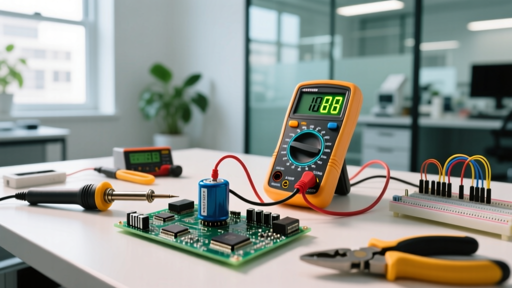

To measure a capacitor with a multimeter, set the dial to the capacitance mode (marked with the -| |- symbol), insert the red lead into the V/Ω/C jack and the black lead into COM, and place the probes across the fully discharged component's terminals. A good reading will fall within the manufacturer's tolerance—typically ±20% of the printed microfarad (µF) or nanofarad (nF) rating. If the meter displays 'OL' (overload) or a value significantly below the minimum threshold, the capacitor is open or degraded and must be replaced.
Meter Setup, Safety Categories, and the Discharge Rule
Before you touch a single probe to a board, you must address the stored energy in the component. Capacitors in power supplies, HVAC systems, and camera flashes can hold lethal charges long after the device is unplugged.
Never short a large electrolytic or mains-rated capacitor with a screwdriver. The instantaneous current spike can weld the tool to the terminals, destroy the capacitor's internal foil, and spray hot electrolyte. Always discharge capacitors using a high-wattage bleed resistor (e.g., a 5W 100Ω ceramic resistor) or a dedicated capacitor discharge tool. Verify the voltage has dropped to < 1V DC with your multimeter's voltage function before switching to capacitance mode.
Meter Setup Block
- Dial Position: Rotate to the capacitance function (-| |-). On auto-ranging meters, this is a single setting. On manual-ranging meters, start at the highest range (e.g., 2000µF) and step down.
- Lead Jacks: Black lead to COM. Red lead to the V/Ω/C (or dedicated µF) jack. Never use the high-current (10A) jack for capacitance testing; the internal shunt will short the component.
- Range Selection: If manual, select a range at least 2x the expected value. Measuring a 470µF cap on the 200µF range will yield an 'OL' (Over Limit) error, which beginners often mistake for a dead part.
Understanding CAT Ratings for Capacitor Testing
Your multimeter's safety category (CAT) rating dictates where it can safely survive transient voltage spikes if you accidentally test a live circuit. According to Fluke safety guidelines, you must match your meter to the environment:
- CAT II: Required for testing capacitors on household appliance boards, PC power supplies, and standard consumer electronics.
- CAT III: Mandatory when measuring large run or start capacitors in HVAC compressors, well pumps, or industrial motor drives connected directly to the building's distribution wiring.
Probe Placement and the Measurement Sequence
For accurate results, capacitors should be tested out-of-circuit. Leaving a component soldered to a PCB introduces parallel resistance and inductance from surrounding traces, which will skew the reading. If you must test in-circuit, you are only looking for dead shorts, not precise capacitance.
- Isolate the Component: Desolder at least one leg of the capacitor to lift it from the PCB pad. For electrolytics, note the polarity (stripe indicates the cathode/negative).
- Zero the Meter: Touch the red and black probes together. The meter should read 0.00 nF or a very small parasitic value (usually 0.01µF to 0.05µF). Note this baseline; you will subtract it from your final reading if measuring very small ceramic capacitors.
- Apply Probes: Place the red probe on the anode (positive) and black on the cathode (negative) for polarized electrolytics. For non-polarized ceramics or film caps, polarity does not matter.
- Wait for Stabilization: Large capacitors (1000µF+) take several seconds to charge via the meter's internal test current. Wait until the reading locks and stops drifting.
Expected Readings: Good, Marginal, and Dead Capacitors
A 'good' reading is strictly defined by the component's printed tolerance. Standard ceramic capacitors (X7R/Y5V) are typically ±10% to ±20%. General-purpose aluminum electrolytics are often rated at ±20% (though some cheap variants allow -20% / +80%). HVAC run capacitors are tightly held to ±6% or ±10%. Below is a reference table for the most common components you will encounter on the bench.
| Component Type & Nominal | Tolerance | Min Acceptable (Good) | Max Acceptable (Good) | Bad / Replace Reading |
|---|---|---|---|---|
| 100nF (0.1µF) Ceramic (X7R) | ±10% | 90.0 nF | 110.0 nF | < 85 nF or OL |
| 10µF Electrolytic (50V) | ±20% | 8.0 µF | 12.0 µF | < 7.5 µF or OL |
| 470µF Electrolytic (25V) | ±20% | 376 µF | 564 µF | < 350 µF |
| 2200µF Filter Cap (Audio) | ±20% | 1760 µF | 2640 µF | < 1600 µF |
| 45µF HVAC Run Capacitor | ±6% | 42.3 µF | 47.7 µF | < 40 µF (Compressor will stall) |
Note: If your meter reads '0.00' or near zero across a large electrolytic, the internal foil has shorted. If it reads 'OL' immediately on a known-good range, the internal connection has opened.
The ESR Blindspot: Why 'Good' Capacitance Can Still Mean a Bad Part
The most common mistake hobbyists make is trusting a multimeter's capacitance reading as the final word on component health. A standard DMM measures capacitance by applying a known DC current and timing how long it takes the voltage to ramp up. This method tells you about the physical plate area and dielectric thickness, but it is completely blind to Equivalent Series Resistance (ESR).
As aluminum electrolytic capacitors age, their internal liquid electrolyte dries out. This causes the ESR to skyrocket. A 1000µF capacitor might still read exactly 1020µF on your Fluke or Brymen multimeter, but if its ESR has climbed from a normal 0.05Ω to 5.0Ω, it will fail to filter high-frequency ripple in a switching power supply. The circuit will overheat, and the capacitor will eventually vent.
According to All About Circuits, a capacitor's true impedance in a high-frequency circuit is dominated by its ESR and parasitic inductance, not its bulk capacitance. Because a standard DMM cannot inject the 100kHz AC signal required to measure ESR accurately, you can easily be fooled by a 'good' reading on a functionally dead part.
DMM Capacitance Mode vs. Dedicated ESR Meter
| Feature | Standard DMM (Capacitance Mode) | Dedicated ESR Meter (e.g., MESR-100) |
|---|---|---|
| Test Signal | Low-frequency DC ramp or slow AC | 100kHz AC sine wave |
| In-Circuit Testing | Poor (parallel paths ruin reading) | Excellent (high freq ignores parallel semiconductors) |
| Detects Dried Electrolyte? | No (Capacitance remains stable) | Yes (ESR spikes dramatically) |
| Primary Use Case | Sorting unmarked caps, verifying new stock, finding dead shorts | Troubleshooting switch-mode power supplies, LCD inverters, and motherboards |
Mistakes That Yield Misleading Readings
- Dielectric Absorption: If you discharge a large capacitor, wait a few minutes, and measure it again, you may see a 'ghost' voltage or a skewed capacitance reading. The dielectric material physically relaxes and releases trapped charge. Always short the leads with a resistor immediately before testing.
- Body Capacitance: When measuring tiny picofarad (pF) ceramics, holding the metal probe tips with your bare fingers introduces your body's parasitic capacitance (often 50pF to 100pF) into the circuit. Use alligator clips or a dedicated SMD test tweezer probe for sub-nF components.
- Ignoring the Baseline: Failing to subtract the probe's parasitic capacitance (usually ~0.05µF) will make you think a 0.1µF ceramic capacitor has degraded to 0.15µF, leading you to throw away a perfectly good part.
Ultimately, a multimeter's capacitance function is an excellent tool for verifying new components, identifying catastrophic failures (shorts/opens), and sorting through your parts bin. But when troubleshooting a failing power supply or an unstable microcontroller reset line, do not let a 'good' microfarad reading stop you from swapping the capacitor or verifying it with a proper 100kHz ESR meter.


