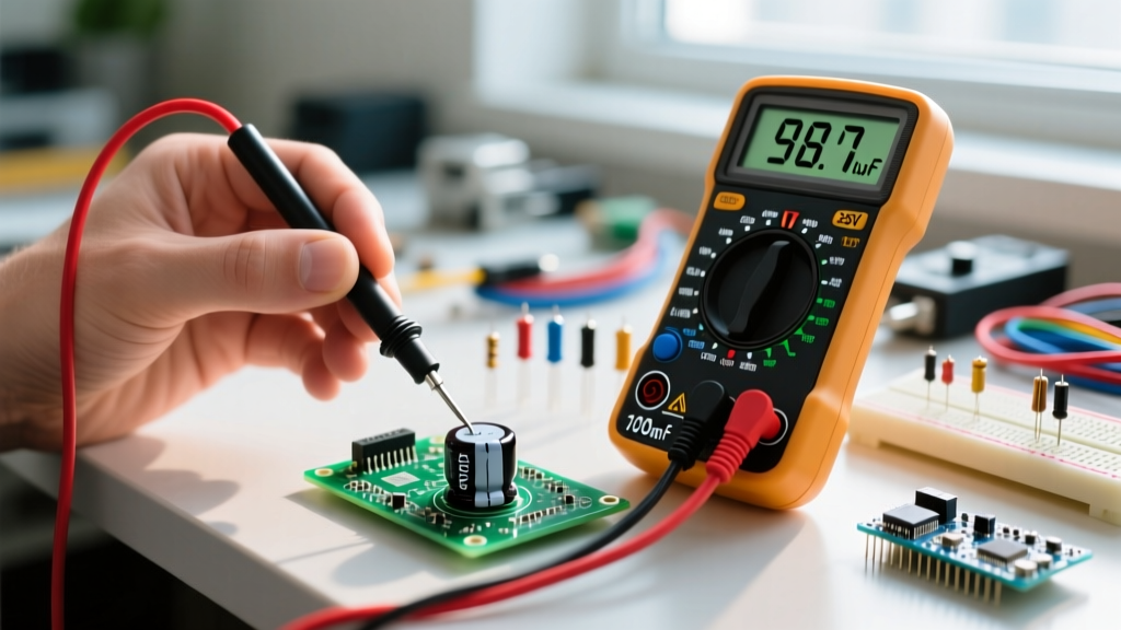

When a motor hums but won't turn, a power supply whines, or an audio amp introduces a nasty 60Hz hum, a failing capacitor is usually the culprit. But unlike resistors, which fail in predictable ways, capacitors can degrade slowly, dry out, or short internally while still looking perfectly fine on the outside. Measuring a capacitor correctly requires more than just slapping multimeter probes across its terminals; it demands an understanding of parasitic capacitance, dielectric absorption, and safe discharge protocols.
The direct answer for measuring a capacitor is to set your digital multimeter (DMM) to the capacitance mode (marked with the -||- symbol), safely discharge the component, isolate it from the circuit, and place the probes across the terminals. A good reading will fall within the manufacturer's stated tolerance—typically ±20% for standard aluminum electrolytics and ±10% for ceramics. However, getting an accurate, trustworthy reading requires strict adherence to the setup and testing procedures outlined below.
Meter Setup and Safety Categories for Capacitor Testing
Before you touch a single probe to a component, your meter must be configured correctly. Measuring capacitance involves the DMM applying a small AC or DC test voltage to the component and calculating the time constant or impedance. If your meter is set up wrong, or if you use it in an environment beyond its safety rating, you risk destroying the meter or yourself.
- Dial Position: Set to Capacitance (look for the
-||-or| |symbol). If your meter requires pressing a 'Mode' or 'Hz' button to access capacitance, do so now. - Lead Jacks: Black lead in
COM. Red lead in theV/Ωor dedicatedCapjack (consult your meter's manual; some meters like the Brymen BM235 use the standard voltage jack, while others require a dedicated high-current/capacitance terminal). - Range: Auto-ranging is preferred. If using a manual-ranging meter, start at the highest range (e.g., 1000µF or 10mF) and step down to avoid overloading the display with an 'OL' (Over Limit) error.
Safety Category (CAT) Requirements: If you are measuring HVAC run capacitors, motor start capacitors, or any capacitor tied to mains-derived power supplies, your meter and probes must be rated for the environment. For 240V HVAC systems and standard 120V/240V branch circuits, you need a CAT III rated meter. For service entrance or outdoor utility-adjacent equipment, CAT IV is required. Never use a CAT II hobby meter for mains-adjacent capacitor testing. Furthermore, never measure capacitance on an energized circuit. The test voltage from the DMM will conflict with the line voltage, instantly blowing the meter's internal HRC fuse or destroying the capacitance-measurement IC.
Step-by-Step: Discharging and Probe Placement
- De-energize and Verify: Turn off the breaker. Use your DMM in AC/DC voltage mode to verify the circuit is dead.
- Discharge Safely: Do not short large capacitors with a screwdriver. The massive instantaneous current spike can weld the screwdriver to the terminals, destroy the capacitor's internal foil, and spray hot metal. Instead, use a 20kΩ, 5W power resistor mounted on insulated alligator clips. Bridge the resistor across the terminals for 10 to 30 seconds until the voltage reads below 1V.
- Isolate the Component: Desolder and lift at least one leg of the capacitor off the PCB. Measuring a capacitor in-circuit often yields false readings because parallel components (like resistors and other caps) create alternate current paths that skew the DMM's calculation.
- Probe Placement:
- Electrolytic/Tantalum (Polarized): Place the red probe on the anode (long lead / positive stripe side) and the black probe on the cathode (short lead / negative stripe). While DMMs output low test voltages, reversing polarity on certain meters can introduce measurement errors or slowly degrade sensitive tantalum dielectrics.
- Ceramic/Film (Non-Polarized): Probe placement does not matter. Place one probe on each lead.
- Wait for Stabilization: Large capacitors (above 100µF) take several seconds for the DMM's internal test current to charge them enough to calculate the value. Wait until the display completely stops drifting before recording the number.
Expected Readings: Good vs. Bad Capacitor Values
A common point of confusion for beginners is knowing what a 'good' reading actually looks like numerically. Manufacturers print a nominal value and a tolerance on the casing. According to industry standards documented by Fluke's capacitance testing guidelines, a capacitor should generally be replaced if it drifts more than 10% to 20% outside its rated tolerance, depending on the application.
| Rated Value & Type | Tolerance | Good Reading Range | Bad Reading (Replace) |
|---|---|---|---|
| 10µF (Electrolytic) | ±20% | 8.0µF – 12.0µF | < 7.5µF (Dry) or OL (Open) |
| 100nF (Ceramic Disc) | ±10% (Z5U/Y5V) | 90nF – 110nF | < 85nF or 0.00nF (Short) |
| 45µF (HVAC Run Cap) | ±6% | 42.3µF – 47.7µF | < 40µF (Weak) or OL (Open) |
| 1000µF (Power Supply) | ±20% | 800µF – 1200µF | < 750µF (High ripple risk) |
The ESR Blind Spot: A standard DMM measures capacitance by timing a charge cycle. However, as aluminum electrolytic capacitors age and their internal electrolyte dries out, their Equivalent Series Resistance (ESR) increases dramatically, even if the actual capacitance value remains within tolerance. A 1000µF power supply filter capacitor might read 980µF on your Fluke 117, but if its ESR has spiked from 0.05Ω to 2.5Ω, it will fail to filter high-frequency switching noise, causing logic resets in microcontrollers. For power supply and motherboard repair, you must supplement your DMM with a dedicated ESR meter (like the MESR-100 or Atlas ESR70), which tests the component at 100kHz to reveal internal drying that capacitance mode completely misses.
Common Mistakes That Give Misleading Readings
Even with a high-end bench meter, operator error can introduce massive inaccuracies. Watch out for these parasitic traps:
- Ignoring Test Lead Capacitance: Standard silicone test leads act as tiny capacitors themselves, typically introducing 20pF to 50pF of parasitic capacitance. If you are measuring a 22pF ceramic capacitor in an RF circuit, your leads will double the reading. Fix: Unplug the leads, press the
REL(Relative) orNULLbutton to zero the meter's internal offset, plug the leads back in, and short the tips together. PressRELagain to subtract the lead capacitance before measuring. - Touching the Metal Probe Tips: The human body is a conductive bag of saltwater with a capacitance of roughly 50pF to 100pF relative to earth ground. If you pinch the metal probe tips and the capacitor leads with your bare fingers while measuring small values (under 1nF), your body will parallel the circuit and inflate the reading. Use alligator clips or PCB hooks for sub-nanofarad measurements.
- Assuming In-Circuit Accuracy: Measuring a capacitor while it is still soldered into a board is a gamble. Parallel decoupling capacitors will add their values together, and parallel resistors will bleed the DMM's test current, causing the meter to read 'OL' or drift endlessly. Always lift one leg of the capacitor for a true capacitance reading.
- Testing Microphonics as Health: Some high-K dielectric ceramics (like X7R and Z5U) exhibit piezoelectric effects. If you tap them or apply mechanical stress while measuring, the capacitance value will fluctuate wildly. This is normal physics, not a sign of a failing component.
Frequently Asked Questions About Measuring a Capacitor
Why does my multimeter show 'OL' when measuring a capacitor?
'OL' stands for Over Limit or Open Loop. When measuring a capacitor, this usually means one of three things: First, the capacitor has failed completely open (an internal foil tear or severed lead). Second, the capacitance value exceeds the maximum range of your meter (e.g., trying to measure a 10,000µF supercapacitor on a meter that maxes out at 2,000µF). Third, if you are measuring in-circuit, a parallel low-resistance path (like a transformer winding or a shorted diode) is draining the meter's test current, preventing it from calculating the time constant. Isolate the component and test again.
Can I measure a capacitor without desoldering it from the board?
You can, but you cannot trust a standard capacitance reading. As Electronics Notes points out, parallel components will skew the DMM's charge-time calculations. However, you can reliably test for dead shorts in-circuit using the DMM's resistance or continuity mode. Furthermore, specialized 'in-circuit ESR testers' inject a high-frequency (100kHz) AC pulse that passes through the capacitor's dielectric but is blocked by parallel inductors and low-value resistors, allowing technicians to identify dried-out electrolytics without desoldering them.
What is the difference between measuring a capacitor and checking continuity?
Continuity mode applies a small DC voltage and checks for a complete low-resistance path (a short circuit). Capacitance mode applies a timed charge/discharge cycle to calculate energy storage. If you put a DMM in continuity mode across a good, discharged capacitor, you will hear a brief 'beep' as the capacitor charges up from the meter's test battery, followed by an 'OL' display once the dielectric blocks the DC current. If the meter beeps continuously, the capacitor has suffered a catastrophic dielectric breakdown and is internally shorted.
Does probe polarity matter when measuring a capacitor?
For non-polarized capacitors (ceramic, film, mica, glass), polarity does not matter; you can place the red and black probes on either lead. For polarized capacitors (aluminum electrolytic, tantalum, niobium), it is best practice to match the red probe to the positive anode and the black probe to the negative cathode. While modern DMMs use very low, safe test voltages that won't instantly explode a reversed electrolytic, applying a reverse bias to a tantalum capacitor can degrade its oxide layer over time, and some meters output a slightly higher DC bias in capacitance mode that can skew the reading if reversed.


