The Math and Reality of a Low Pass Capacitor Filter
A low pass capacitor filter is the most fundamental signal-conditioning circuit on your bench. In its simplest RC (resistor-capacitor) configuration, it allows DC and low-frequency signals to pass while attenuating high-frequency noise. The theoretical cutoff frequency ($f_c$), where the signal power drops by half (-3dB), is calculated as:
$f_c = \frac{1}{2 \pi R C}$
On paper, a 10kΩ resistor and a 1µF capacitor yield a cutoff frequency of 15.9 Hz. But on the bench, a capacitor is never just a static number. It is a complex electrochemical component with parasitic resistance (ESR), parasitic inductance (ESL), and a dielectric material whose capacitance shifts wildly with temperature, applied voltage, and age. If you treat the capacitor in your low pass filter as an ideal component, you will eventually chase ghosts on your oscilloscope.
Decoding Physical Markings and Voltage Derating
Before you can select the right part, you need to read what is sitting in your bin. Through-hole and surface-mount ceramics use the EIA 3-digit capacitance code. The first two digits are the significant figures, and the third is the multiplier (number of zeros), expressed in picofarads (pF).
- 104: 10 × 10⁴ pF = 100,000 pF = 100 nF = 0.1 µF
- 105: 10 × 10⁵ pF = 1,000,000 pF = 1 µF
- 473: 47 × 10³ pF = 47,000 pF = 47 nF
For voltage ratings, look for a letter-number combo often stamped on electrolytics, tantalums, or larger film caps. The letter represents the base voltage, and the number is the multiplier. According to All About Circuits standard reference charts:
- 1J: 6.3 × 10¹ = 63V
- 1H: 5.0 × 10¹ = 50V
- 1E: 2.5 × 10¹ = 25V
- 1C: 1.6 × 10¹ = 16V
Dielectric Showdown: Which Type for Which Job?
The dielectric material inside the capacitor dictates its behavior in a low pass filter. Choosing the wrong dielectric is the number one cause of filter drift. Here is how the common types stack up for filtering applications.
| Dielectric Type | Construction / Material | Typical Tolerance | Tempco / Temp Range | Best Filter Use |
|---|---|---|---|---|
| C0G / NP0 | Class I Ceramic (Paraelectric) | ±1% to ±5% | 0 ±30 ppm/°C (-55 to 125°C) | Precision ADC references, audio crossovers, RF filters |
| X7R | Class II Ceramic (Ferroelectric) | ±10% to ±20% | ±15% (-55 to 125°C) | General purpose DC smoothing, PWM-to-analog, power rail decoupling |
| Y5V | Class II Ceramic (Ferroelectric) | -20% to +80% | +22% / -82% (-30 to 85°C) | Avoid in filters. Use only for bulk decoupling where exact value is irrelevant |
| Polyester (Mylar) | Metallized Film | ±5% to ±10% | ±10% (-55 to 125°C) | Audio signal path, high-voltage analog filters, low microphonic circuits |
| Aluminum Electrolytic | Etched Foil with Liquid Electrolyte | ±20% | High drift, limited to 85°C/105°C | Low-frequency power supply ripple filtering (sub-100Hz) |
Bench Story: When the "Perfect" Filter Failed
Let us look at a real-world scenario where ignoring dielectric physics caused a headache on the bench.
The Setup: I needed to smooth a 500Hz, 5V PWM signal from a microcontroller into a clean 0-5V DC analog voltage to drive a motor controller's speed input. I designed an RC low pass capacitor filter with a 10kΩ resistor and a 1µF capacitor.
The Numbers: Using $f_c = \frac{1}{2 \pi R C}$, the target cutoff was 15.9 Hz. At the 500Hz PWM fundamental frequency, a first-order filter should provide roughly -30dB of attenuation, reducing the AC ripple to an unnoticeable ~15mV on the DC baseline.
The Outcome: When I hooked up the oscilloscope, the DC output had a massive 120mV peak-topeak 500Hz ripple riding on it. The motor controller was whining audibly, interpreting the ripple as rapid speed changes.
What Went Wrong: I had grabbed a 1µF 0805 ceramic capacitor from my bin without checking the dielectric code. It was a Y5V part. Y5V dielectrics suffer from extreme DC bias capacitance drop. At a 5V DC bias, a 1µF Y5V capacitor loses up to 75% of its nominal capacitance, dropping to just 0.25µF.
Because the actual capacitance in-circuit was 0.25µF, the real cutoff frequency shifted up to 63.6 Hz. The attenuation at 500Hz plummeted to just -17.9dB, letting the PWM ripple straight through. I swapped the Y5V for a 2.2µF X7R ceramic (which holds about 80% of its value at 5V, yielding a stable ~1.7µF in-circuit), and the ripple vanished.
Visual Failure Modes on the PCB
Capacitors in low pass filters do not just drift; they fail catastrophically. Knowing what a failing filter cap looks like saves hours of troubleshooting. According to failure analysis data from Analog Devices and field return studies, look for these visual symptoms:
- MLCC Flex Cracks: Visual Symptom: A microscopic hairline crack running parallel to the terminal ends of a surface-mount ceramic capacitor, often only visible under 10x magnification. Circuit Effect: Intermittent dead shorts when the PCB flexes, or a complete open circuit that silently disables your low pass filter, letting high-frequency noise destroy your downstream ADC.
- Electrolytic Drying / Venting: Visual Symptom: The top rubber vent bulges outward, or crusty brown electrolyte leaks from the base. Circuit Effect: Equivalent Series Resistance (ESR) spikes from a fraction of an ohm to tens of ohms. The capacitor stops filtering high-frequency noise and begins dissipating ripple current as heat, accelerating its own death.
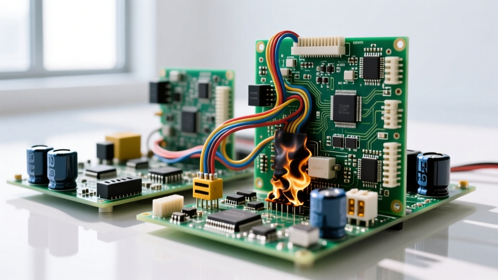
- Tantalum Thermal Runaway: Visual Symptom: A charred, blackened crater on the PCB where the capacitor used to be, accompanied by a sharp ozone smell. Circuit Effect: A dead short across the power rail. Tantalum caps fail short and can ignite if the power supply can deliver enough current to sustain the fault. Never use tantalums for low-impedance power rail filters without strict current limiting.
The Substitution Playbook: Swapping Parts Safely
Supply chain shortages happen. When your exact BOM capacitor is out of stock, you cannot just grab any part with the same microfarad rating. Follow this numbered protocol to substitute safely without compromising your filter response.
- Never Substitute Down in Voltage: If the BOM calls for a 25V cap, you can use a 50V cap, but never a 16V cap. Higher voltage parts are physically larger, so check your PCB footprint clearances before committing.
- Match the Temperature Coefficient (Tempco): If the original design specified a C0G/NP0 for a precision filter, do not substitute an X7R. The X7R will introduce microphonic distortion (piezoelectric effect) and capacitance drift as the board heats up, ruining the filter's phase response.
- Compensate for DC Bias in Class II Ceramics: If you must swap an X5R for an X7R, or if you are forced to use a smaller physical package (e.g., swapping a 1206 for an 0805), the smaller part will suffer worse DC bias capacitance loss. Fix: Double the nominal capacitance value to ensure the derated in-circuit value meets your $f_c$ target.
- Watch the ESR in Active Filters: If your low pass filter is part of an active Sallen-Key topology or feeds an LDO regulator, the circuit might rely on the specific ESR of a tantalum or electrolytic cap for stability. Substituting a low-ESR ceramic can cause high-frequency oscillation. If you must use a ceramic in these cases, add a 1Ω series resistor to artificially mimic the ESR of the original part.
Designing a robust low pass capacitor filter requires looking past the schematic symbol. By decoding the physical markings, respecting the physics of the dielectric material, and planning for real-world failure modes, you ensure your circuit performs on the bench exactly as it did in the simulator.