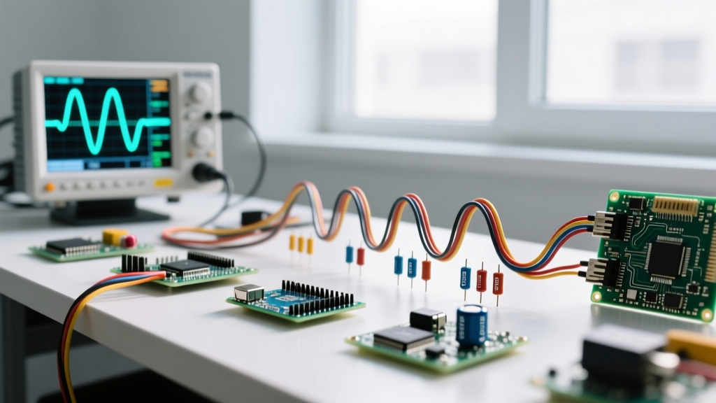
A logic gate truth table defines the ideal boolean relationship between inputs and outputs, but real-world circuit design requires mapping those abstract 1s and 0s to physical silicon. Whether you are wiring up a 74HC08 quad AND gate on a breadboard or routing a CD4011B NAND gate on a custom PCB, the abstract table is only the starting point. You must also account for logic family voltage thresholds, propagation delays, and fan-out limitations.
This reference provides the complete, bookmark-friendly truth tables for standard 2-input combinational logic, mapped directly to the most common 74xx (TTL/CMOS) and 4000 (CMOS) series ICs.
The Master Logic Gates Truth Tables and IC Mapping
The following table consolidates the boolean outputs for all standard 2-input logic gates. This matrix conforms to the standard logic symbols and definitions outlined in IEEE/ANSI Std 91-1984 and standard digital electronics curricula.
| Input A | Input B | AND | NAND | OR | NOR | XOR | XNOR |
|---|---|---|---|---|---|---|---|
| 0 (Low) | 0 (Low) | 0 | 1 | 0 | 1 | 0 | 1 |
| 0 (Low) | 1 (High) | 0 | 1 | 1 | 0 | 1 | 0 |
| 1 (High) | 0 (Low) | 0 | 1 | 1 | 0 | 1 | 0 |
| 1 (High) | 1 (High) | 1 | 0 | 1 | 0 | 0 | 1 |
While the boolean math remains identical across all silicon families, the physical IC you purchase dictates your voltage thresholds and speed. Below is the quick-jump reference for the most queried 2-input gate part numbers across the three dominant hobbyist and industrial logic families.
| Gate Function | 74HC Series (CMOS, 2V-6V) | 74HCT Series (TTL-Compatible, 4.5V-5.5V) | 4000B Series (CMOS, 3V-15V) | Typical $t_{pd}$ (at 5V, 15pF) |
|---|---|---|---|---|
| Quad 2-Input AND | 74HC08 | 74HCT08 | CD4081B | 12 ns |
| Quad 2-Input NAND | 74HC00 | 74HCT00 | CD4011B | 10 ns |
| Quad 2-Input OR | 74HC32 | 74HCT32 | CD4071B | 12 ns |
| Quad 2-Input NOR | 74HC02 | 74HCT02 | CD4001B | 12 ns |
| Quad 2-Input XOR | 74HC86 | 74HCT86 | CD4030B / CD4070B | 14 ns |
Translating Ideal Tables to Real Silicon: Thresholds and Derating
A truth table assumes instantaneous transitions and perfect voltage levels. Real silicon requires you to interpret which column applies to your installation regarding input voltage thresholds ($V_{IH}$ and $V_{IL}$) and how physical loading derates the baseline timing.
Voltage Thresholds: 74HC vs. 74HCT
The most common mistake in mixed-voltage systems is misinterpreting the logic high threshold. If you are driving a 5V logic gate from a 3.3V microcontroller (like an ESP32 or Raspberry Pi Pico), you must look at the $V_{IH}$ (Input Voltage High) specification:
- 74HC (High-speed CMOS): $V_{IH}$ is typically 70% of VCC. At 5V VCC, the chip requires 3.5V to register a logical "1". A 3.3V MCU output will fail to trigger it reliably.
- 74HCT (High-speed CMOS, TTL inputs): $V_{IH}$ is fixed at 2.0V minimum, regardless of the 5V VCC. This column applies directly to installations where 3.3V microcontrollers interface with 5V peripherals.
How Capacitive Loading Derates Propagation Delay
The baseline propagation delay ($t_{pd}$) listed in Table 2 assumes a minimal 15pF capacitive load. In a real installation, PCB traces, breadboard parasitics, and the input capacitance of downstream gates add load. This is how derating rows modify the base value:
For a standard 74HC08 at 5V, the datasheet specifies a derating factor of roughly 0.4 ns per pF of additional load. If your PCB trace and the fan-out of three downstream gates total 50pF, you must add 35pF to the baseline test condition.
Calculation: 35pF × 0.4 ns/pF = 14 ns of additional delay. Your real-world $t_{pd}$ is not the 12 ns listed in the table, but 26 ns. If you are chaining gates in a high-speed clock path, this derating accumulates and can cause severe phase shift or setup-time violations.
What the Truth Table Cannot Tell You
Truth tables are purely mathematical abstractions. They define the steady-state boolean logic but omit the physical realities of semiconductor design. When debugging a circuit that "should work according to the truth table," check these three physical failure modes.
1. Floating Inputs and Shoot-Through Current
A truth table only accounts for defined 0s and 1s. It does not account for a disconnected (floating) pin. In older 74LS (TTL) logic, a floating input naturally biases high due to internal pull-up resistors. However, in 74HC and 4000B CMOS logic, a floating input acts as an antenna. It will pick up electromagnetic noise and oscillate rapidly between high and low.
Because CMOS gates use complementary P-channel and N-channel MOSFETs, this rapid oscillation causes both transistors to conduct simultaneously during the transition—a phenomenon called shoot-through. This results in massive $I_{DD}$ current spikes, overheating the IC, and causing brownouts on your power rail. Rule: Never leave a CMOS logic input floating; always tie unused inputs to VCC or GND via a 10kΩ resistor.
2. Asymmetric Current Sourcing vs. Sinking
The truth table output "1" implies the gate can power an LED. In standard 74LS TTL, this is a trap. A standard 74LS gate can sink (pull to ground) up to 8mA when the output is Low, but can only source (push from VCC) about 0.4mA when the output is High. If you wire an LED with a current-limiting resistor from VCC to the gate output, it will light up brightly when the truth table says "0". If you wire it from the gate output to GND, it will barely glow when the truth table says "1". Modern 74HC CMOS is more symmetrical (typically ±4mA at 5V), but always verify the $I_{OH}$ and $I_{OL}$ columns in the datasheet before driving loads directly.
3. Metastability and Transition Glitches
When inputs A and B of an XOR gate transition simultaneously from (0,1) to (1,0), the truth table dictates the output should remain "1". In physical silicon, the internal transistor switching speeds are never perfectly matched. One input may register the transition nanoseconds before the other, causing the gate to momentarily pass through the (0,0) state. This generates a microsecond-wide "glitch" (a false 0) on the output. If that output is tied to the clock input of a flip-flop or a counter, that invisible glitch will trigger an unintended state change. In high-reliability designs, truth tables must be supplemented with Karnaugh maps and hazard-free logic design to eliminate these transition glitches.