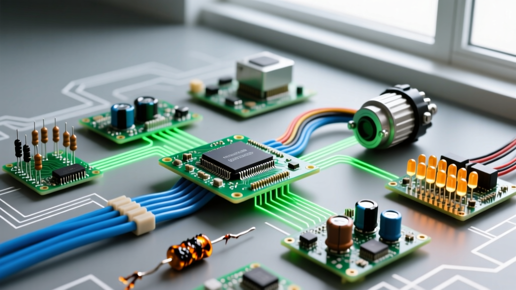
Learning how to design printed circuit boards (PCBs) is not about memorizing ECAD software shortcuts; it is about translating physical electrical constraints into copper geometry. The fastest path to competence is taking a verified breadboard circuit, laying it out in a modern, free tool like KiCad 8, and ordering a small batch from a quick-turn fab house. However, moving from solderless prototyping to a manufactured board introduces parasitics, thermal limits, and assembly realities that breadboards hide. This guide bridges that gap with exact trace dimensions, migration checklists, and first-spin testing protocols.
The Breadboard-to-PCB Migration Checklist
Solderless breadboards are excellent for logic verification but terrible for high-frequency, high-current, or precision analog circuits. A standard breadboard contact introduces roughly 2pF to 5pF of parasitic capacitance and up to 100mΩ of contact resistance. When you migrate to a PCB, you must actively correct the bad habits these parasitics mask.
Mistakes That Survive the Migration
Which mistakes survive from breadboard to PCB? The most common is missing local decoupling. On a breadboard, the long, messy jumper wires accidentally act as distributed inductors and capacitors, sometimes providing enough high-frequency filtering to keep a microcontroller stable. On a PCB with a solid ground plane, a missing 100nF X7R MLCC placed within 2mm of a microcontroller's VCC pin will result in brownouts and erratic ADC readings.
Another survivor is ignoring return paths. Beginners often route a signal trace to a component but rely on the software's auto-router or a distant ground via to complete the circuit. This creates large loop areas that act as slot antennas, radiating EMI or picking up noise. Every critical signal trace must have an unbroken ground plane directly beneath it on the adjacent layer.
- Replace all electrolytic decoupling caps with 100nF (0.1µF) and 10µF X7R/X5R MLCCs placed physically adjacent to IC power pins.
- Eliminate "air wires" by utilizing a continuous copper pour on the bottom layer tied to GND.
- Verify all CMOS inputs have explicit pull-up or pull-down resistors; floating inputs that "happened to work" on a breadboard will oscillate and overheat on a PCB.
- Upgrade 1/4W through-hole resistors to 0805 or 0603 SMD footprints to reduce parasitic lead inductance.
Sizing Traces: Current, Copper Weight, and Thermal Limits
Knowing what trace width a specific current needs is the most critical physical constraint in layout. Trace ampacity is governed by the IPC-2221 standard, which calculates width based on copper thickness, allowable temperature rise, and whether the trace is on an external or internal layer. Internal layers have roughly half the current-carrying capacity of external layers because they are encased in FR4 fiberglass, which acts as a thermal insulator.
Standard hobbyist and prototype boards typically use 1 oz (35 µm) copper. If your design includes motor drivers, high-power LEDs, or lithium battery charging paths, you should specify 2 oz (70 µm) copper when ordering from your fab house.
Trace Width vs. Current Table (External Layers, 10°C Rise)
The following table provides baseline trace widths for external layers assuming a 10°C temperature rise above ambient. For internal layers, double these widths.
| Current (A) | 1 oz Cu Width (mil / mm) | 2 oz Cu Width (mil / mm) | Typical Application |
|---|---|---|---|
| 0.5A | 11 mil (0.28 mm) | 7 mil (0.18 mm) | Logic ICs, I2C/SPI pull-ups |
| 1.0A | 20 mil (0.51 mm) | 12 mil (0.30 mm) | ESP32 VCC rails, small servos |
| 2.0A | 46 mil (1.17 mm) | 26 mil (0.66 mm) | USB-C PD 5V/3A lines, stepper coils |
| 3.0A | 77 mil (1.96 mm) | 42 mil (1.07 mm) | LiPo charge paths, DC motor feeds |
| 5.0A | 143 mil (3.63 mm) | 78 mil (1.98 mm) | Main battery input, high-power MOSFET drains |
Note: For currents exceeding 5A, consider using polygon pours instead of standard traces, and apply solder mask openings to allow tinning (flooding the trace with solder) to increase effective cross-sectional area.
Assembly, Soldering, and Workshop Safety
Transitioning to surface-mount devices (SMD) requires precise thermal management. The most common beginner failure mode is using excessive heat, which delaminates the copper pad from the FR4 substrate or destroys the internal die of a semiconductor.
Alloy Selection and Temperature Profiles
For prototyping and repair, use Sn63/Pb37 (63% Tin / 37% Lead) eutectic solder. It melts sharply at 183°C and flows beautifully. Set your soldering station (e.g., Hakko FX-888D or Pinecil) to 320°C - 340°C. If you are designing for commercial production or RoHS compliance, you must design for SAC305 (96.5% Sn, 3.0% Ag, 0.5% Cu) lead-free alloy. SAC305 melts at 217°C and requires an iron temperature of 350°C - 380°C, alongside a more aggressive flux.
Always use a flux pen or tacky flux (ROL0 or ROL1 classification for no-clean, low-halide) when soldering SMD components. Flux removes oxidation and lowers the surface tension of the molten solder, preventing bridging on 0.5mm pitch TSSOP or QFP packages.
Testing Your First Spin: A Powered Verification Sequence
When your first batch of boards arrives from the fab house, the instinct is to immediately plug in the power supply and upload code. Doing this risks turning a minor layout error into a catastrophic short that destroys your PC's USB port or starts a fire. Follow this staged verification sequence to test a first spin board safely.
Step 1: Visual and DMM Inspection (Unpowered)
- Inspect the board under a magnifying lamp or digital microscope for solder bridges, tombstoned capacitors, or missing vias.
- Set your digital multimeter (DMM) to continuity or resistance mode.
- Probe the main VCC rail to GND. A healthy digital board should read > 10 kΩ (or show a forward diode drop of ~0.4V if reverse-polarity protection diodes are present). If it reads < 5 Ω, you have a solder bridge or a backwards-mounted polarized capacitor. Do not apply power.
- Check continuity from your microcontroller's GND pin to the main ground plane to ensure the thermal pad is properly soldered.
Step 2: Current-Limited Power Ramp-Up
Never power a first-spin board directly from a PC USB port or an unregulated wall wart. Use a bench power supply with adjustable Over-Current Protection (OCP).
- Set the bench supply to the board's nominal voltage (e.g., 3.3V or 5.0V).
- Set the current limit (OCP) to 50mA. A dormant microcontroller and a few sensors should draw between 15mA and 30mA. If the board immediately pulls 50mA and the supply drops into constant-current (CC) mode, you have a fault.
- Monitor the voltage on the board's test points with a second DMM. If the supply reads 5.0V but the board test point reads 1.2V, you have a high-resistance fault (cold solder joint or undersized trace) dropping the voltage.
Step 3: Thermal and Signal Verification
Once the board powers up stably within expected current limits:
- Use a thermal camera (like an InfiRay P2 Pro) or a thermocouple to scan the board. Voltage regulators, MOSFETs, and microcontrollers should remain within 10°C of ambient at idle. Any component exceeding 60°C at idle indicates a short, a floating CMOS input oscillating at high frequency, or an inadequate thermal via array.
- Connect your logic analyzer or oscilloscope to verify I2C/SPI bus rise times. If the edges are rounded rather than square, your pull-up resistors are too weak for the bus capacitance of your new PCB layout.
By treating PCB design as a physical engineering discipline rather than just a digital drawing exercise, you bridge the gap between theoretical circuit diagrams and reliable, manufacturable hardware. For comprehensive layout rules and footprint generation, refer to the official KiCad documentation and always cross-reference your trace geometries with your chosen fab house's specific design rule check (DRC) capabilities.