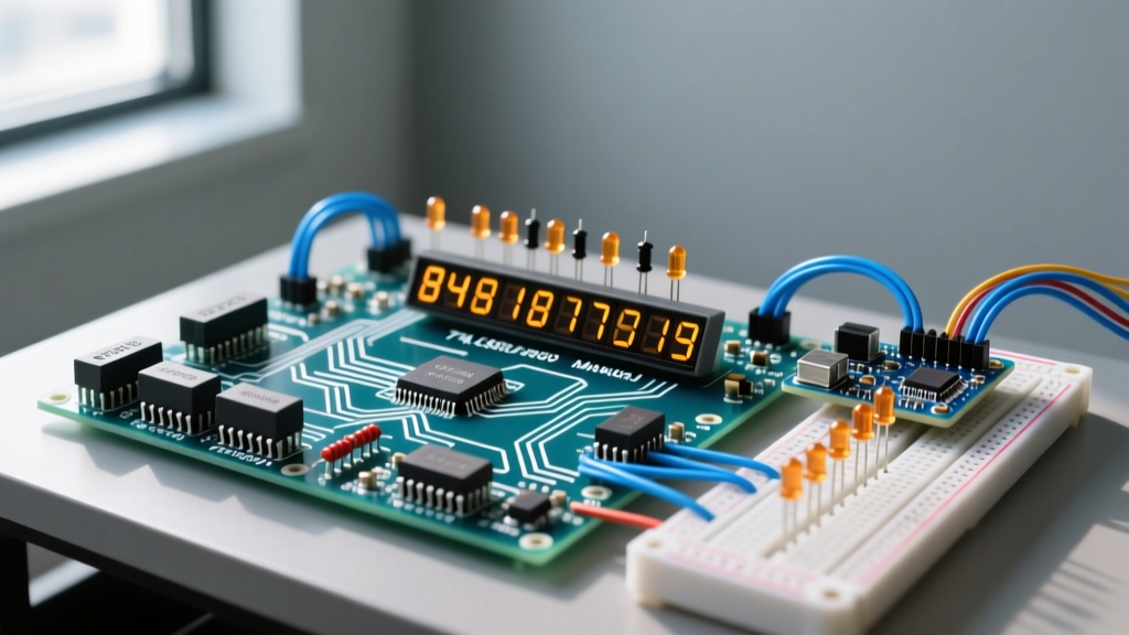
To drive a large-format (4-inch to 12-inch) LED 7 segment display reliably without flicker, thermal throttling, or blown logic, you must abandon simple current-limiting resistors. The direct answer for scoreboard, architectural, and industrial panel applications is to use a constant-current sink driver like the Texas Instruments TLC5940 paired with P-channel MOSFETs for digit multiplexing, fed by a 24V constant-voltage power supply. This topology handles the high forward voltages of large segment strings while keeping heat out of the display face.
When scaling up from standard 0.56-inch breadboard indicators to high-luminosity architectural digits, the electrical rules change. You are no longer just switching logic levels; you are managing lighting circuits, power factor, and thermal derating. Here is the bench-tested framework for designing your drive electronics.
Efficacy and Power: Mapping Lumens to Segment Arrays
Large-format displays achieve high visibility by chaining multiple SMD LEDs in series per segment. A common mistake is selecting LEDs based purely on millicandela (mcd) ratings without calculating the thermal load. High efficacy (lumens per watt) is critical because any wattage not converted to light becomes heat trapped inside the sealed polycarbonate or epoxy display face.
| LED Package | Typical Wattage | Luminous Flux (per LED) | Efficacy (lm/W) | Typical 7-Seg Application |
|---|---|---|---|---|
| 5mm Through-Hole (Oval) | 0.06W (20mA) | ~3.5 lm | ~58 lm/W | Small indoor indicators (< 2") |
| 2835 SMD (Mid-Power) | 0.2W to 0.5W | ~25 lm (at 60mA) | ~125 lm/W | Medium indoor/outdoor (2" - 4") |
| 5050 SMD (High-Power) | 1.0W to 3.0W | ~110 lm (at 350mA) | ~110 lm/W | Large scoreboards & gas signs (6"+) |
| 3030 SMD (Architectural) | 0.5W to 1.0W | ~65 lm (at 150mA) | ~130 lm/W | High-visibility transit & highway signs |
Efficacy Context: Notice that the 2835 and 3030 packages offer superior lm/W ratios compared to older 5050 high-power chips. In a 6-digit display using 3030s, you might push 15W of total electrical power. If you drop to a less efficient package, that 15W might yield the same lumens but require 22W of input power. That extra 7W of heat will raise the internal enclosure temperature by 15°C to 20°C, accelerating lumen depreciation and risking epoxy yellowing.
Dimming, Flicker, and the PWM Beat Frequency
Flicker in multiplexed LED displays is almost always a beat frequency issue—the interference pattern created when your digit multiplexing (MUX) frequency clashes with your PWM dimming frequency or the AC ripple from your power supply.
Why Flicker Happens and the Fix
If you multiplex a 6-digit display at 500Hz (meaning each digit refreshes at roughly 83Hz) and apply a 100Hz PWM dimming signal to control brightness, the overlapping duty cycles will create visible rolling bars or a strobe effect on camera.
To eliminate beat-frequency flicker, your PWM dimming frequency must be at least 5 times higher than your MUX refresh rate, or perfectly synchronized via hardware timer interrupts. For a 1kHz MUX rate, push your PWM dimming to 5kHz or higher. The TLC5940 handles this natively via its GSCLK pin, allowing PWM frequencies up to 30MHz.
Dimmer Compatibility Criteria
When integrating large displays into architectural lighting, you may need to dim them via a wall-box AC dimmer feeding the DC power supply.
- Trailing-Edge vs. Leading-Edge: Always specify trailing-edge (ELV) dimmers for switch-mode LED power supplies. Leading-edge (TRIAC) dimmers cause severe inrush spikes and audible buzzing in the PSU's input capacitors.
- Minimum Load Check: Trailing-edge dimmers require a minimum load to keep their internal MOSFETs biased correctly. A single 4-inch display digit might only draw 4W. If your dimmer requires a 15W minimum load, the display will drop out or strobe at low dimming levels. You must either parallel enough digits to exceed the minimum load or install a bleeder resistor / dummy load (e.g., a 10W wirewound resistor) across the AC line.
- DC-Side Min Load: If using a constant-current buck driver (like the Diodes Inc. AL8860) on the DC side, ensure the total forward voltage ($V_f$) of your segment string is at least 2V below the supply rail to maintain regulation. A 24V supply driving a 22V string leaves insufficient headroom for the driver's internal sense resistor and switching node.
Circuit Impact Math: Inrush, Power Factor, and Thermal Limits
Scaling a display from a single prototype digit to a 12-panel scoreboard introduces severe inrush currents and thermal constraints that will destroy undersized components.
Inrush Current Calculation
Large LED arrays require substantial bulk decoupling capacitance on the DC bus to prevent voltage sag during multiplexed segment switching. If your 12-digit array uses 4,700µF of total bulk capacitance and your 24V power supply ramps up in 2 milliseconds, the inrush current is:
I = C × (dV / dt) = 0.0047F × (24V / 0.002s) = 56.4 Amps
This 56A spike will trip standard thermal breakers and degrade the power supply's rectifier diodes. The Fix: Implement an NTC thermistor (like the Ametherm SL32 2R015) on the AC input of the PSU, or use an active soft-start circuit with a MOSFET and RC delay on the DC bus.
Heat and Enclosure Constraints
The epoxy or polycarbonate face of a 7-segment display has a strict Glass Transition Temperature ($T_g$), typically around 110°C to 125°C. If the internal ambient temperature exceeds this, the optical resin clouds and the wire bonds to the LED die experience shear stress from CTE (Coefficient of Thermal Expansion) mismatch.
For high-power arrays, you must calculate the thermal resistance ($R_{\theta JA}$) of your PCB. Use an aluminum-core (MCPCB) backplane for digits drawing more than 10W per square foot, and ensure your constant-current driver ICs are mounted on the rear side of the PCB with thermal vias, completely isolated from the LED heat zone.
The Decision Tree: Picking Your Driver and Topology
Do not guess your driver topology. Use this decision matrix to lock in your Bill of Materials (BOM) based on your specific digit count and current requirements.
| Display Scale | Segment Current | Topology Required | Recommended Driver IC |
|---|---|---|---|
| Small (1-2 digits, < 1") | < 20mA per segment | Direct Multiplex (Logic level) | MAX7219 (SPI) |
| Medium (4 digits, 2" - 4") | 20mA - 80mA per segment | Constant Current Sink + NPN/PNP MUX | TLC5940 (16-ch) + ULN2803 |
| Large (6+ digits, 6" - 12") | 100mA - 1A+ per segment | Constant Current Sink + P-FET MUX | TLC5940 + Si2301 P-FETs |
| Architectural (High Voltage AC) | AC Mains Direct | Triac / Relay Isolated | Opto-isolated TRIAC (MOC3021) |
The Concrete Pick: Large-Format Default BOM
If you are building a standard 6-digit, 4-inch outdoor scoreboard display running at 150mA per segment, stop evaluating alternatives and use this exact proven topology:
- Segment Drivers: Daisy-chain three TI TLC5940 ICs (providing 48 constant-current channels). Set the reference current ($I_{max}$) to 150mA using a 1.24kΩ resistor on the IREF pin.
- Digit Multiplexing: Use Si2301 P-channel MOSFETs to switch the 24V common anode of each digit. The TLC5940 cannot source 24V, so the P-FET handles the high-side switching, controlled by an N-channel level shifter (like a 2N7000) from your microcontroller's GPIO.
- Power Supply: A 24V, 150W Mean Well constant-voltage LED driver (e.g., LRS-150-24) with a built-in active PFC (Power Factor > 0.95) to satisfy commercial utility requirements.
This setup guarantees flicker-free 12-bit grayscale dimming, handles the 24V headroom required for long segment strings, and keeps the high-side switching thermals completely off your logic board.
By respecting the thermal limits of the display enclosure, matching your PWM and MUX frequencies to avoid beat interference, and sizing your bulk capacitance to handle inrush, your display will maintain uniform brightness and survive years of outdoor operation without a single failed segment.