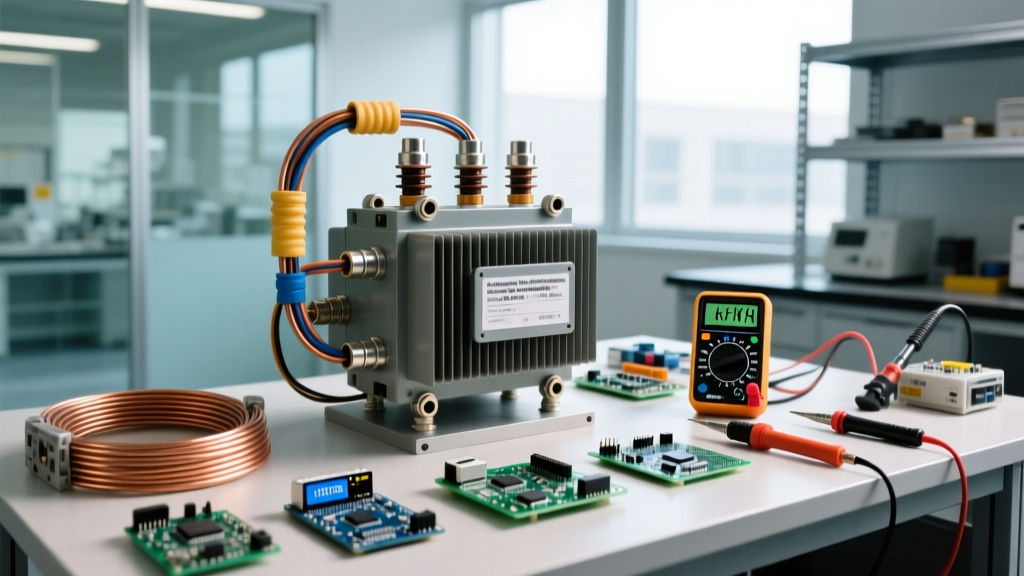

The kVA rating on a transformer defines its maximum apparent power capacity, dictating the total voltage and current it can safely handle regardless of the load's power factor. When you look at a transformer nameplate, this number is the absolute thermal ceiling of the equipment. It tells you exactly how much electromagnetic stress the copper or aluminum windings can endure before insulation breakdown or catastrophic overheating occurs.
Decoding the kVA Rating on a Transformer Nameplate
In practical circuit design, the kVA rating changes how you size your overcurrent protection and feeder wires. It is the fundamental limiting factor for the physical current flowing through the transformer's windings. Heat generation in a transformer is governed by the formula P = I²R. Because heat is proportional to the square of the current, the transformer 'cares' only about the total amperes passing through its coils, not how much of that current is actually performing useful work.
The most common mistake DIYers and junior engineers make is confusing kVA (kilovolt-amperes) with kW (kilowatts). Kilowatts measure real power—the actual energy converted into mechanical work, heat, or light. Kilovolt-amperes measure apparent power—the vector sum of real power and reactive power (kVAR). If you size a transformer based solely on the kW rating of your loads without accounting for reactive power, you will undersize the unit and trip your primary fuses or melt the secondary windings.
The Math: Apparent Power vs. Real Power
To understand why the kVA rating on a transformer dictates your physical installation limits, we have to look at power factor (PF). Power factor is the ratio of real power (kW) to apparent power (kVA). A purely resistive load, like a bank of incandescent heaters, has a PF of 1.0. Inductive loads, like AC motors and compressors, typically have a PF between 0.80 and 0.90.
Think of power like water flowing through a pipe to turn a waterwheel. The kVA is the total volume of water flowing through the pipe (the current the transformer must supply). The kW is the water that actually hits the paddles to do useful work. The kVAR (reactive power) is the water that sloshes back and forth in the pipe, doing no work but still requiring the pipe (the transformer windings) to be large enough to handle the total flow.
Worked Numeric Example: Sizing a 50 kVA Transformer
Let's assume you are installing a single-phase 50 kVA transformer with a 240V secondary to power a small workshop.
- Find the Maximum Secondary Current:
Using our formula: Amps = (kVA × 1000) / Volts
Amps = 50,000 / 240 = 208.33 Amps.
This means your secondary conductors and breaker must be sized to handle at least 208.33A continuously. - Calculate Real Power at Unity Power Factor (PF = 1.0):
If your shop only runs resistive space heaters, your real power capacity is 50 kVA × 1.0 = 50 kW. - Calculate Real Power at Inductive Power Factor (PF = 0.85):
If your shop is full of table saws, air compressors, and dust collectors, your average PF might be 0.85.
Your real power capacity drops to 50 kVA × 0.85 = 42.5 kW.
Notice the critical takeaway: Even though you are only getting 42.5 kW of real work out of the transformer, the windings are still carrying the full 208.33 Amps. The transformer is operating at 100% of its thermal kVA limit. If you try to pull 50 kW of real power from this 0.85 PF load, you will actually demand 58.8 kVA of apparent power, overloading the transformer by nearly 18%.
Where You Meet Transformer kVA Ratings in Practice
You will encounter transformer kVA sizing constraints in three primary real-world scenarios:
1. Sizing Subpanels and Service Entrances
If you are feeding a 200-Amp residential subpanel at 240V, the maximum apparent power is (240 × 200) / 1000 = 48 kVA. You would select the next standard size up, which is a 50 kVA transformer. Per NEC Article 450 guidelines, the primary and secondary overcurrent protection must be carefully calculated based on this exact kVA rating to prevent nuisance tripping during transformer magnetizing inrush current, which can briefly spike to 12 times the rated full-load current.
2. Non-Linear Loads and K-Factor Ratings
Modern facilities are packed with Variable Frequency Drives (VFDs), LED drivers, and server power supplies. These non-linear loads draw current in abrupt pulses rather than smooth sine waves, creating harmonic distortion. Harmonics cause severe eddy current losses in the transformer core, generating excess heat even if the total kVA load is below the nameplate rating. If your facility has high harmonic content, you must specify a K-rated transformer (e.g., K-4, K-13, or K-20). A standard 75 kVA transformer might overheat at 60% load under severe harmonics, whereas a 75 kVA K-13 transformer is built with heavier gauge windings and specialized core designs to dissipate that specific harmonic heat profile.
3. Utility Billing vs. Infrastructure Sizing
Commercial utility bills often feature a 'demand charge' based on peak kW, but penalize you if your power factor drops below 0.90. Why? Because the utility company has to size their distribution transformers, transmission lines, and switchgear based on the total kVA (the total current) you pull from the grid. If you draw 100 kVA but only do 70 kW of work due to a terrible 0.70 power factor, the utility is wasting infrastructure capacity to deliver your reactive power. According to the U.S. Department of Energy, distribution transformer losses account for a significant percentage of total grid transmission losses, making proper kVA management and power factor correction vital for grid efficiency.
Quick Reference: Transformer kVA to Full-Load Amps
Use this table to instantly find the maximum secondary current for common standard transformer sizes. (Source: All About Circuits - AC Power)
| Transformer kVA | 120V (1-Phase) Amps | 240V (1-Phase) Amps | 208V (3-Phase) Amps | 480V (3-Phase) Amps |
|---|---|---|---|---|
| 15 kVA | 125.0 A | 62.5 A | 41.6 A | 18.0 A |
| 30 kVA | 250.0 A | 125.0 A | 83.2 A | 36.1 A |
| 50 kVA | 416.7 A | 208.3 A | 138.7 A | 60.1 A |
| 75 kVA | 625.0 A | 312.5 A | 208.1 A | 90.2 A |
| 112.5 kVA | 937.5 A | 468.8 A | 312.2 A | 135.3 A |
Frequently Asked Questions About Transformer kVA
Can I overload a transformer's kVA rating if my power factor is low?
No. A transformer's kVA rating is an absolute thermal limit based on the physical current (Amperes) flowing through the windings. If your load has a low power factor (e.g., 0.70), you are drawing high current for very little real work (kW). The transformer windings will still experience I²R heating based on that high current. Exceeding the kVA rating will degrade the insulation and eventually cause a short circuit, regardless of how few kilowatts of real power you are consuming.
How do I convert a transformer's kVA rating to amps?
To convert kVA to amps, multiply the kVA rating by 1,000 to get volt-amperes (VA), then divide by the system voltage. For single-phase systems, the formula is Amps = (kVA × 1000) / Volts. For three-phase systems, you must also divide by the square root of 3 (1.732), making the formula Amps = (kVA × 1000) / (Volts × 1.732). Always use the secondary voltage of the transformer for this calculation to find your maximum load-side amperage.
Why do utilities bill me in kW but size my transformer in kVA?
Utilities bill commercial customers in kW because kilowatts represent the actual real energy (fuel burned at the power plant) you consume to do work. However, the utility must size their physical infrastructure—transformers, transmission lines, and switchgear—based on kVA. kVA represents the total current flowing through their wires. If you have a poor power factor, you force the utility to supply high current (kVA) for low real energy (kW), wasting their infrastructure capacity. This is why utilities impose financial penalties if your power factor drops below 0.90.
What happens if I connect a 60Hz transformer to a 50Hz supply at the same kVA?
You cannot safely run a 60Hz transformer at its rated voltage on a 50Hz supply. The magnetic flux density in the transformer core is inversely proportional to frequency. Dropping the frequency from 60Hz to 50Hz increases the core flux by 20%, driving the core into magnetic saturation. This causes a massive spike in magnetizing current, severe overheating, and loud humming, even if the connected load is well below the kVA rating. To use a 60Hz transformer on a 50Hz system, you must reduce the applied voltage by exactly 16.7% (the ratio of 50/60), which inherently reduces the available kVA capacity.


