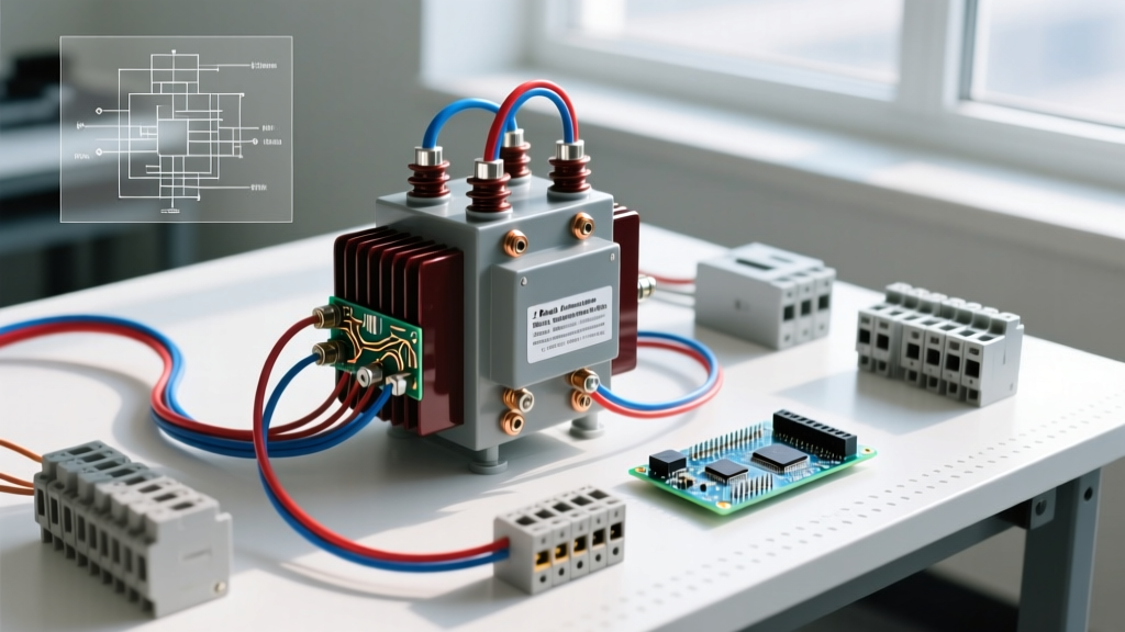
Inductor coils store energy in a magnetic field and inherently oppose changes in current, acting as a mechanical flywheel for electrons. In a typical 12V-to-5V buck converter switching at 500kHz, a 10µH inductor coil limits the AC ripple current to roughly 1.4A, smoothing the DC output while passing the average load current. Selecting the right coil requires matching the core material to your operating frequency and ensuring the saturation current ($I_{sat}$) exceeds your peak load. If you push an inductor past its saturation point, its inductance collapses, and it behaves like a short piece of wire, often destroying the driving MOSFET.
Inductor Coil Construction and Selection Matrix
The physical core material dictates almost every critical parameter of an inductor coil, from its self-resonant frequency (SRF) to how it handles high DC bias. Below is a data-dense comparison of the four primary inductor constructions you will encounter on the bench or in commercial SMPS (Switch-Mode Power Supply) designs.
| Core Type | Construction Details | Typical Tolerance | Tempco (ppm/°C) | Saturation Profile | Primary Application |
|---|---|---|---|---|---|
| Air Core | Self-supporting wound copper wire; no magnetic core material. | ±2% to ±5% | +30 to +50 | None (Linear) | RF circuits, VHF/UHF filters, >10MHz switching. |
| Ferrite Drum (Unshielded) | MnZn or NiZn ferrite bobbin with exposed wire windings. | ±10% to ±20% | Varies by mix | Hard knee (sudden drop) | General-purpose power, low-cost DC-DC, <3MHz. |
| Iron Powder | Carbonyl iron particles distributed in a non-magnetic binder. | ±10% to ±15% | Low / Stable | Soft knee (gradual drop) | High DC bias applications, PFC chokes, high current. |
| Shielded Molded (SMD) | Ferrite or iron composite encased in epoxy/magnetic potting. | ±20% to ±30% | Moderate | Very High / Soft | High-density DC-DC, noise-sensitive logic rails, automotive. |
Selection Criteria: Choose air core when operating above 10MHz where ferrite core losses would generate excessive heat. Choose unshielded ferrite for cost-sensitive, low-current auxiliary rails where EMI (Electromagnetic Interference) is not a concern. Choose iron powder when your circuit sees massive DC bias currents, as the distributed air gaps prevent hard saturation. Choose shielded molded (like the Würth WE-LQS or Coilcraft XEL series) for high-current, high-density boards where magnetic flux leakage could couple noise into adjacent sensitive analog traces.
Decoding Inductor Coil Markings and Codes
Unlike resistors and capacitors, inductor markings are notoriously inconsistent across manufacturers. However, two dominant coding systems cover 90% of the parts you will desolder or procure.
SMD 3-Digit and 'R' Notation
Surface-mount power inductors typically use a 3-digit code where the first two digits are the significant figures, and the third digit is the multiplier (number of zeros). The base unit is always microhenries (µH).
100= 10 × 10^0 = 10µH (Beginners often misread this as 100µH).101= 10 × 10^1 = 100µH.472= 47 × 10^2 = 4700µH (or 4.7mH).
For values under 10µH, the letter R acts as the decimal point:
4R7= 4.7µH.R47= 0.47µH (470nH).R10= 0.10µH (100nH).
Axial Color Bands
Through-hole axial inductors (like the classic Vishay IM or Bourns 78F series) use the standard 4-band resistor color code, but the resulting number is read in microhenries, not ohms. A brown-black-brown-gold band sequence translates to 1-0-1 (100µH) with a ±5% tolerance. Note that a silver tolerance band on an inductor typically denotes ±10%, which is the most common tolerance for off-the-shelf power chokes.
Failure Modes and Visual Diagnostics
Inductors rarely fail without a physical or thermal catalyst. When troubleshooting a dead SMPS or a blown MOSFET, inspect the inductor coil for these specific failure modes.
1. Thermal Runaway and Melted Enamel
The Physics: The copper windings have a DC resistance (DCR). If the RMS current exceeds the part's thermal rating ($I_{rms}$), the $I^2R$ losses heat the wire. The thin polyurethane or polyimide enamel insulation melts, causing adjacent turns to short together. This reduces the total number of active turns, dropping the inductance and increasing ripple current, which accelerates the heating in a runaway loop.
Visual Symptoms: Discolored or blistered epoxy potting on shielded SMD parts. A distinct smell of burning varnish. On unshielded drum cores, the copper wire may look blackened or charred.
Bench Test: Measure the DCR with a milliohm meter. A 10µH shielded coil like the Coilcraft XEL1020-100ME should read around 14mΩ. If it reads near 0Ω, the internal windings have shorted.
2. Core Cracking (Mechanical/Thermal Shock)
The Physics: Ferrite is a brittle ceramic. Rapid temperature changes during wave soldering, or mechanical flexing of the PCB, can fracture the core. A crack introduces an unintended physical air gap into the magnetic circuit.
Visual Symptoms: Hairline fractures on the ferrite drum or shield casing. Sometimes visible only under 10x magnification.
Bench Test: The inductance will measure lower than nominal on an LCR meter, and the part will emit audible high-frequency whining or cause severe EMI spikes on an oscilloscope due to flux leaking from the crack.
3. Magnetic Saturation (The Invisible Failure)
The Physics: If the peak current exceeds $I_{sat}$, the core's magnetic domains are fully aligned. The inductance plummets, and the coil becomes a low-value resistor. The switching transistor sees a near-dead short to ground.
Visual Symptoms: None on the inductor itself. The MOSFET will likely explode or the PCB trace will vaporize.
Bench Test: Capture the switch-node current with a current probe. If the current waveform shows a sharp, exponential hockey-stick spike at the end of the ON-time rather than a clean linear ramp, the inductor is saturating.
Safe Substitution Rules When the Exact Part is Missing
When repairing a board or prototyping without the exact BOM part, you cannot simply swap a 10µH inductor for any other 10µH inductor. For authoritative design guidance, reference resources like the Coilcraft Inductor Basics guide or application notes from Analog Devices on buck converter magnetics. Follow this strict parameter hierarchy to substitute safely:
- Inductance (L): Must be within ±20% of the original. Going slightly higher reduces ripple but slows transient response; going lower increases ripple and core loss.
- Saturation Current ($I_{sat}$): MUST be greater than your peak inductor current ($I_{out(max)} + \frac{\Delta I_L}{2}$). Never substitute a part with a lower $I_{sat}$.
- Thermal Current ($I_{rms}$): MUST be greater than your maximum continuous DC load. This is the current that causes a 40°C temperature rise.
- DCR (DC Resistance): Should be equal to or lower than the original to maintain efficiency and prevent overheating.
- Self-Resonant Frequency (SRF): Must be significantly higher than your switching frequency (typically SRF > 10 × $f_{sw}$) to ensure the part behaves inductively, not capacitively.
Worked Substitution Example: 12V to 3.3V Buck Converter
Assume you are repairing a 12V-to-3.3V logic rail pulling 2A, switching at 500kHz. The original unshielded 10µH drum inductor burned out. You need to select a modern shielded replacement.
Step 1: Calculate Ripple and Peak Current.
Duty cycle $D = \frac{3.3V}{12V} = 0.275$.
Targeting a standard 30% ripple ($0.3 \times 2A = 0.6A$), the required inductance is:
$L = \frac{V_{out} \times (1 - D)}{\Delta I_L \times f_{sw}} = \frac{3.3 \times 0.725}{0.6 \times 500,000} = 7.97\mu H$.
We select the standard value of 10µH.
Step 2: Recalculate Actual Ripple with 10µH.
$\Delta I_L = \frac{3.3 \times 0.725}{10\mu H \times 500,000} = 0.478A$.
Peak current $I_{pk} = I_{out} + \frac{\Delta I_L}{2} = 2A + 0.239A = 2.24A.
Step 3: Define Minimum Specs for the Substitute.
We need $I_{sat} > 2.5A$ (adding a 10% safety margin) and $I_{rms} > 2.0A$.
Searching the distributor catalog, we find the Coilcraft XEL1020-100ME. It is a 10µH shielded composite core inductor. Its datasheet specifies an $I_{sat}$ (at 20% drop) of 5.5A and an $I_{rms}$ of 4.1A, with a DCR of just 13.7mΩ. This part exceeds all requirements, runs cool, and its shielded construction will eliminate the EMI noise that likely plagued the original unshielded drum core.