
The RC Impedance Triangle: Your First Line of Defense Against Noise
When debugging a noisy sensor line or a jittery ADC reading, the solution almost always comes down to manipulating the impedance triangle RC circuit. In a series or parallel resistor-capacitor network, the impedance triangle defines the geometric relationship between pure resistance ($R$), capacitive reactance ($X_C$), and total impedance ($Z$). The formula $Z = \sqrt{R^2 + X_C^2}$ isn't just textbook theory; it is the exact mathematical mechanism that allows a simple passive filter to shunt high-frequency switching noise to ground while passing your DC or low-frequency signal untouched.
Because capacitive reactance is inversely proportional to frequency ($X_C = \frac{1}{2\pi fC}$), the shape of the impedance triangle physically changes depending on the frequency of the signal passing through it. At DC, $X_C$ is theoretically infinite, and the triangle collapses into a flat line where $Z = R$. At high frequencies (like the 500 kHz switching noise from a nearby buck converter), $X_C$ approaches zero, the triangle becomes extremely tall and narrow, and the capacitor acts as a near-short circuit to ground. Understanding this dynamic shift is how you engineer signal integrity on a budget.
Identifying the Dominant Coupling Path in RC Networks
Before you can fix noise, you must identify how it is entering your circuit. In low-voltage, high-impedance RC networks, capacitive coupling is the dominant noise path. When a noisy trace (like a PWM line or a switching node) runs parallel to a high-impedance sensor trace, the parasitic capacitance between the traces allows displacement current ($I = C \frac{dv}{dt}$) to inject noise directly into your signal node. Because the node impedance is high (e.g., $R > 10k\Omega$), even picoamps of injected current create measurable voltage spikes ($V = I \times R$).
Conversely, conductive coupling dominates in low-impedance nodes. If your RC filter shares a ground return path with a high-current motor driver, ground bounce will inject noise directly through the conductive copper. Radiated (magnetic) coupling is rarely the primary issue for standard low-power RC signal lines unless your trace forms a large loop area directly adjacent to an unshielded power inductor.
If capacitive coupling is severe, you might reach for a shielded cable. However, shielding an RC sensor line without proper ground termination will destroy your signal integrity. The shield must be terminated to the signal ground at the ADC/receiver side only (preferably using a 360-degree circumferential clamp, not a pigtail). Grounding the shield at both ends creates a ground loop, turning your shield into an antenna for conductive common-mode noise, which will completely bypass your RC filter.
Ranked Fixes: From Pennies to Precision
What is the cheapest fix that actually works for high-frequency noise on an RC node? Adding a surface-mount ceramic capacitor. Below is a decision-tree table ranking the most effective fixes based on cost, implementation effort, and the specific noise profile they address.
| Fix Strategy | Estimated Cost | Best For (Noise Profile) | Limitations & Gotchas |
|---|---|---|---|
| 1. Add 100nF X7R MLCC (Parallel to load) | $0.02 | High-frequency (>10kHz) EMI and switching noise on high-Z nodes. | Can introduce phase shift in feedback loops. X7R dielectrics lose capacitance under DC bias. |
| 2. Series Ferrite Bead (e.g., Murata BLM18PG121SN1D) | $0.15 | Creating a pi-filter or RLC network to target specific high-frequency resonance. | Not a universal cure. Beads saturate and lose inductance if DC current exceeds their rating (often just 100-300mA). Use only for low-current signal lines. |
| 3. Increase R, Decrease C (Maintain same $f_c$) | $0.00 | Reducing thermal (Johnson-Nyquist) noise and minimizing capacitive loading on the source. | Higher R increases susceptibility to capacitive coupling from external EMI. Trade-off required. |
| 4. Active Sallen-Key Filter (Op-Amp based) | $1.50+ | When you need a sharp roll-off (2nd or 4th order) and low output impedance to drive an ADC. | Requires dual power rails or rail-to-rail op-amps. Adds board space and active component noise. |
Proving the Fix: Before and After Measurement Methods
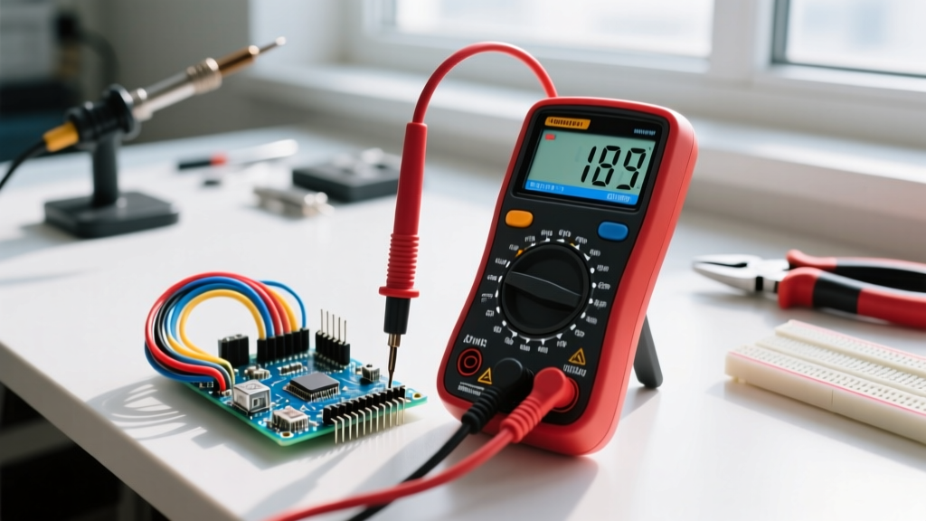
Applying a fix is only half the job; you must prove the impedance triangle is behaving as expected. Do not rely on "it looks cleaner on the scope." Use this numbered protocol to quantify the improvement with a meter or oscilloscope (such as a Rigol DS1054Z or Siglent SDS1202X-E).
- Establish the Baseline (AC RMS): Connect your oscilloscope probe across the load resistor (the 'R' in your RC circuit). Set the scope to AC Coupling and enable the built-in AC RMS measurement. Record this baseline noise voltage (e.g., 45 mV RMS).
- Identify the Dominant Frequency: Switch the scope to FFT (Fast Fourier Transform) mode. Identify the peak frequency of the noise (e.g., a sharp spike at 500 kHz from a nearby buck converter).
- Calculate the Required $X_C$: To attenuate the 500 kHz noise by at least -20dB (a factor of 10), your capacitor's reactance ($X_C$) at 500 kHz must be roughly 1/10th of the resistor's value. If $R = 10k\Omega$, you need $X_C = 1k\Omega$ at 500 kHz. Using $C = \frac{1}{2\pi f X_C}$, you calculate a required capacitance of ~318 pF. A standard 1nF ceramic cap will provide even greater attenuation.
- Apply the Fix and Re-measure: Solder the 1nF capacitor directly across the load resistor (minimize parasitic lead inductance by keeping the leads short). Re-measure the AC RMS voltage. A successful fix should show the RMS noise dropping from 45 mV to < 5 mV.
- Verify Phase Shift (Optional but recommended): If this RC circuit is part of a control loop, inject a known sine wave from a function generator. Use the scope's XY mode or dual-trace delay measurement to verify the phase angle ($\theta = \arctan(-X_C / R)$) matches your theoretical impedance triangle calculations at the signal frequency.
Frequently Asked Questions: RC Impedance and Signal Integrity
How does the impedance triangle RC circuit change at the cutoff frequency?
At the -3dB cutoff frequency ($f_c = \frac{1}{2\pi RC}$), the magnitude of the capacitive reactance ($X_C$) exactly equals the resistance ($R$). In the impedance triangle, this creates a perfect 45-degree right triangle where the total impedance $Z$ is $R \times \sqrt{2}$ (or roughly $1.414 \times R$). The signal is attenuated by 3dB (about 29.3% voltage drop), and the phase shift is exactly -45 degrees. This is the transition point where the circuit shifts from acting primarily resistive to primarily capacitive.
Why does my RC filter introduce a DC offset when filtering PWM noise?
If you are using an RC low-pass filter to extract an analog DC voltage from a PWM signal, the theoretical DC output should be $V_{out} = V_{pwm} \times DutyCycle$. However, if your microcontroller's GPIO pin has asymmetric drive strength (e.g., the pull-up MOSFET has a different $R_{DS(on)}$ than the pull-down MOSFET), the charging and discharging currents through the RC network are unequal. This asymmetry interacts with the capacitor's dielectric absorption, causing a slight DC offset error. To fix this, buffer the PWM signal with a CMOS logic gate or an op-amp before it hits the RC filter to ensure symmetric drive impedance.
Can I use the impedance triangle to calculate the phase shift of my noisy signal?
Yes, the phase angle $\theta$ of the impedance triangle directly dictates the time delay (phase shift) introduced to your signal. The formula is $\theta = \arctan(\frac{-X_C}{R})$. If you are designing an anti-aliasing filter for an ADC sampling at 1 MSPS (as detailed in the TI Precision Labs ADC Series), you must ensure the phase shift at your maximum signal frequency does not cause destructive interference or group delay distortion. Always calculate $\theta$ at your signal frequency, not your noise frequency.
What happens to the RC impedance triangle if I use an electrolytic instead of a ceramic capacitor?
Electrolytic capacitors have high Equivalent Series Resistance (ESR) and Equivalent Series Inductance (ESL). At high frequencies (typically above 50 kHz), the ESL begins to dominate, and the component stops acting like a capacitor and starts acting like an inductor. The impedance triangle breaks down because the reactance becomes inductive ($+X_L$) rather than capacitive ($-X_C$). For high-frequency signal integrity and noise shunting, always use low-ESR ceramic MLCCs (like C0G/NP0 for precision or X7R for general decoupling). Reserve electrolytics for bulk low-frequency power supply filtering. For deeper mathematical modeling of these AC behaviors, refer to the All About Circuits AC theory guide.