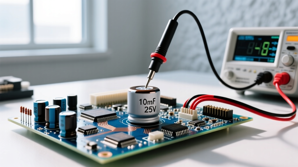
A voltmeter must always be connected in parallel across the component, wires, or test points you are measuring. You never break the circuit to insert a voltmeter. Because a digital multimeter (DMM) in voltage mode has an extremely high internal impedance (typically 10 MΩ), connecting it in parallel allows it to sample the electrical potential difference between two points without drawing significant current or altering the circuit's behavior.
The Core Rule: Always Connect in Parallel
To understand how a voltmeter is connected in a circuit, you must understand the difference between measuring potential (voltage) and measuring flow (current). Voltage is a differential measurement—it only exists between two points.
When you set your meter to measure voltage, an internal 10 MΩ (10,000,000 ohms) resistor is switched into the circuit. If you were to mistakenly connect the voltmeter in series (by breaking the circuit and putting the meter inline like an ammeter), that 10 MΩ resistance would choke the circuit. The current would drop to microamps, the load would fail to operate, and the meter would simply read the full open-circuit source voltage. By connecting in parallel, the 10 MΩ impedance sits alongside the load, drawing a negligible amount of current (usually less than a milliamp) while accurately sensing the potential difference.
Meter Setup Block: Dial, Jacks, and CAT Ratings
Before touching any probes to a circuit, your meter must be configured correctly. A misconfigured meter is the leading cause of blown internal fuses and catastrophic arc flashes.
| Setting | Correct Configuration | Why It Matters |
|---|---|---|
| Lead Jacks | Black to COM, Red to VΩ | Putting the red lead in the 'A' or 'mA' jack creates a near dead-short across your test points. |
| Dial Position (DC) | V⎓ or VDC | Used for batteries, solar arrays, and PCB logic (steady polarity). |
| Dial Position (AC) | V~ or VAC | Used for mains power, transformers, and HVAC (alternating polarity). |
| Range | Auto-ranging or highest manual range | Prevents overloading the ADC if the voltage is higher than expected. |
Safety Category (CAT) Ratings
When measuring mains voltage, the CAT rating of your meter and probes dictates your safety margin against transient voltage spikes (like a lightning strike on the grid or a heavy motor switching off). According to Fluke's safety guidelines and IEC 61010 standards:
- CAT II: Plug-in appliances and standard receptacles.
- CAT III: Distribution panels, fixed motors, and branch circuit wiring.
- CAT IV: Service entrance equipment, utility meters, and outdoor overhead lines.
Step-by-Step Probe Placement for DC and AC
Proper probe placement ensures you are measuring the exact potential difference across the intended load or source.
1. DC Circuit (e.g., 12V LED Strip or Arduino VCC)
- Identify Polarity: Locate the positive (VCC/+) and negative (GND/-) terminals.
- Place Black Probe: Touch the black (COM) probe to the negative or ground terminal.
- Place Red Probe: Touch the red (VΩ) probe to the positive terminal.
- Read: If the reading shows a negative sign (e.g., -12.0V), your probes are reversed. Swap them. The magnitude is still correct, but the polarity is inverted.
2. AC Circuit (e.g., 120V Wall Receptacle)
- Identify Slots: The shorter slot is Hot (Line), the longer slot is Neutral, and the U-shaped hole is Ground.
- Measure Hot-to-Neutral: Insert one probe into the short slot, the other into the long slot. (Polarity does not matter for AC RMS readings).
- Measure Hot-to-Ground: Move the second probe to the U-shaped ground hole to verify the equipment grounding conductor is bonded and carrying no fault current.
- Measure Neutral-to-Ground: Place probes in the long slot and U-shaped hole to check for objectionable neutral current or voltage drop.
Expected Readings: Good vs. Bad Values
Knowing how to connect the meter is only half the battle; you must know what the numbers mean. The following table uses standard nominal values and ANSI C84.1 tolerances for AC systems.
| Test Point | Meter Setting | Expected Good Reading | Bad / Fault Reading | What the Bad Reading Means |
|---|---|---|---|---|
| 12V Lead-Acid Battery (Resting) | VDC | 12.6V - 12.8V | < 11.9V | Deeply discharged or sulfated cell. |
| 120V Receptacle (Hot to Neutral) | VAC | 114V - 126V | < 110V or > 130V | Excessive voltage drop (undersized wire) or utility transformer tap issue. |
| 120V Receptacle (Neutral to Ground) | VAC | < 2.0V | > 5.0V | Loose neutral connection upstream or overloaded shared neutral. |
| 240V Dryer Outlet (Hot to Hot) | VAC | 228V - 252V | ~120V | One leg of the 240V breaker has tripped or a feeder wire is broken. |
| Arduino 5V Pin to GND | VDC | 4.8V - 5.2V | < 4.5V | USB cable voltage drop or failing onboard voltage regulator. |
Troubleshooting Misleading Readings and Fatal Mistakes
Even when connected in parallel, environmental factors and user errors can yield false data or destroy equipment.
The "Ghost Voltage" Trap
When measuring long runs of AC cable (like 3-way switch travelers or abandoned wires in a conduit), your high-impedance (10 MΩ) voltmeter might read 40V to 80V on a dead wire. This is capacitive coupling—the live wire running parallel to the dead wire acts as a capacitor, inducing a phantom voltage. Because the meter draws almost zero current, it registers this phantom potential. The fix: Switch your meter to LoZ (Low Impedance) mode, which drops the internal resistance to roughly 3 kΩ, bleeding off the phantom charge and correctly reading 0V.
The Amps Jack Catastrophe
If you leave the red probe in the 10A (Amps) jack and connect the probes in parallel across a 120V AC receptacle, you are placing a near-zero ohm shunt resistor directly across the mains. This creates a dead short. In a cheap meter, this will cause an internal arc flash, melting the probes and potentially injuring you. In a quality meter, the high-rupture-capacity (HRC) fuse will violently blow to save your life, but the meter is out of commission until you replace the $15 specialty fuse.
Dirty Probe Tips
While voltage measurements are less sensitive to probe resistance than current measurements, a buildup of oxidation or flux on the probe tips can introduce 5 to 10 ohms of series resistance. When measuring low-voltage DC logic (like a 3.3V ESP32 GPIO pin), this can skew your reading by tens of millivolts. Always wipe probe tips with isopropyl alcohol before bench work.
Decision Path: Choosing the Right Meter and Range
Use this decision tree to select the correct meter type and features for your specific testing environment.
| Your Primary Environment | Critical Feature Needed | Required CAT Rating |
|---|---|---|
| PCB Debugging, Arduino, 12V DC Automotive | High resolution (mV range), fast continuity beep | CAT II or un-rated (bench only) |
| HVAC Troubleshooting, Home Receptacles, Lighting | LoZ (Low Impedance) mode, True RMS, Non-Contact Voltage | CAT III 600V minimum |
| Industrial Panels, Service Entrances, 480V 3-Phase | HRC fuses, heavy-duty probe guards, IP67 rating | CAT IV 600V / CAT III 1000V |