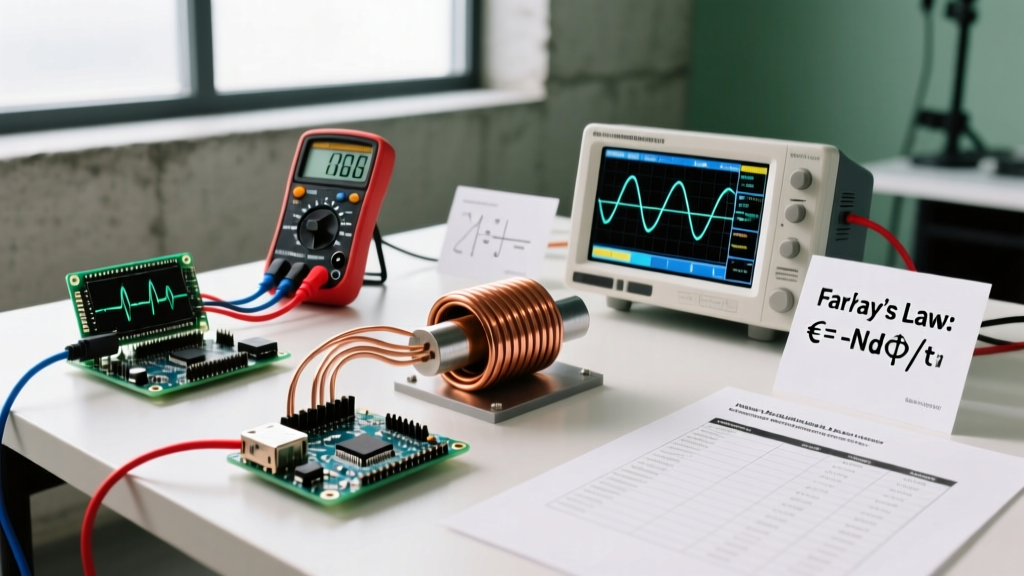

Induced current is the flow of electrical charge generated in a conductor when it experiences a changing magnetic field, calculated by dividing the induced electromotive force (EMF) by the circuit's total resistance. If you are trying to figure out how to find induced current in a bench project or a theoretical circuit, you need to combine Faraday’s Law of Induction with basic Ohm’s Law. The master equation is I = ℰ / R, where the induced EMF (ℰ) is defined as ℰ = -N(ΔΦ / Δt).
Understanding this relationship is critical for designing transformers, sizing dynamic braking resistors for motors, and troubleshooting unwanted back-EMF spikes that fry microcontrollers. Below, we break down the exact variables, run a real-world numeric calculation, and clarify the most common pitfalls makers and students hit when working with electromagnetic induction.
The Core Variables: What Dictates Induced Current?
Before you can calculate the current, you need to understand the physical parameters that drive the induced EMF and the resistance that limits it. The magnitude of the induced current scales linearly with the number of coil turns and the rate of magnetic flux change, but it is strictly limited by the total ohmic resistance of the closed loop.
| Parameter | Symbol | SI Unit | Real-World Benchmark | Effect on Induced Current |
|---|---|---|---|---|
| Number of Turns | N | unitless | 50 (small relay) to 2,000 (transformer primary) | Linear increase (Double turns = double EMF) |
| Magnetic Flux Change | ΔΦ | Weber (Wb) | 0.005 Wb (ferrite bead) to 2.5 Wb (large stator) | Linear increase (Stronger Δ field = higher EMF) |
| Time Interval | Δt | seconds (s) | 2 ms (fast MOSFET switch) to 1.5 s (manual movement) | Inverse relationship (Faster change = higher EMF) |
| Circuit Resistance | R | Ohms (Ω) | 0.05 Ω (thick busbar) to 150 Ω (AWG 30 magnet wire) | Inverse relationship (Higher R = lower current) |
Worked Numeric Example: Calculating Coil Current
Let’s move from abstract formulas to a concrete bench scenario. Suppose you are building a custom electromagnetic brake and need to know the peak induced current when the magnetic field collapses.
• Coil Turns (N): 200
• Cross-sectional Area (A): 0.05 m²
• Initial Magnetic Field (B_initial): 1.2 T (typical N52 neodymium surface field)
• Final Magnetic Field (B_final): 0 T (field collapses)
• Time Interval (Δt): 0.1 seconds
• Total Circuit Resistance (R): 10 Ω (coil wire + external load)
Step 1: Calculate the Change in Magnetic Flux (ΔΦ)
Magnetic flux (Φ) is the product of the magnetic field (B) and the area (A) it passes through perpendicularly (Φ = B × A). We only care about the change in flux.
- ΔB = 1.2 T - 0 T = 1.2 T
- ΔΦ = ΔB × A = 1.2 T × 0.05 m² = 0.06 Wb
Step 2: Calculate the Induced EMF (ℰ)
Using Faraday's Law, we plug in the turns, flux change, and time. We will drop the negative sign for now since we are calculating the absolute magnitude of the current.
- ℰ = N × (ΔΦ / Δt)
- ℰ = 200 × (0.06 Wb / 0.1 s)
- ℰ = 200 × 0.6 = 120 Volts
Step 3: Calculate the Induced Current (I)
Now apply Ohm's Law. The induced EMF acts exactly like a battery voltage driving current through the loop's resistance.
- I = ℰ / R
- I = 120 V / 10 Ω = 12 Amps
The Result: The collapsing field induces a brief 12A current pulse. If your switching transistor or diode isn't rated for this transient surge (or if you lack a flyback diode), that 120V/12A spike will instantly destroy your driving circuitry. For deeper theoretical background on these transient spikes, refer to the Georgia State University HyperPhysics database on Faraday's Law.
Where You Meet Induced Current in Practice
Induced current isn't just a textbook concept; it fundamentally alters how real-world circuits and mechanical systems behave. Here is where you will encounter it on the jobsite or at the workbench, and exactly what it changes in your installation.
1. Variable Frequency Drives (VFDs) and Motor Braking
When a VFD commands an AC motor to decelerate, the motor's mechanical inertia keeps the rotor spinning. The motor acts as a generator, inducing a massive current back into the drive's DC bus. What it changes: This induced current raises the DC bus voltage. If the drive lacks a dynamic braking resistor to dissipate this energy as heat, the overvoltage will trip the drive's fault protection or blow the bus capacitors.
2. Induction Cooktops and Eddy Current Heating
An induction stove uses a high-frequency alternating current in a copper coil to create a rapidly changing magnetic field. This field induces localized currents (eddy currents) directly inside the ferromagnetic cookware. What it changes: The induced current encounters the electrical resistance of the steel or iron pan, converting electrical energy directly into thermal energy (I²R heating) without the stove surface itself getting hot.
3. Transformer Inrush Currents
When you first energize a large transformer, the sudden application of AC voltage forces the magnetic core to rapidly establish a flux field. What it changes: This rapid ΔΦ/Δt induces a massive, asymmetrical inrush current in the primary winding that can be 10 to 15 times the normal full-load current. This is why you must size primary fuses and breakers with time-delay characteristics to prevent nuisance tripping during startup.
Common Confusions: Voltage vs. Current and Flux vs. Change
When learning how to find induced current, makers frequently mix up the underlying physics. Let's clear up the two most common misconceptions, referencing Khan Academy's breakdown of electromagnetic induction for further reading.
| Misconception | The Reality | Practical Example |
|---|---|---|
| "A stronger magnet induces more current." | A static magnetic field, no matter how strong, induces exactly zero current. Only the rate of change (ΔΦ / Δt) matters. | Holding a 1.4 T N52 neodymium magnet perfectly still inside a 5,000-turn coil yields 0.00 A. You must move it to generate current. |
| "Induced EMF and Induced Current are the same thing." | Induced EMF (Voltage) is the potential to push electrons. Induced current is the actual flow, which requires a closed path and depends on resistance. | An open-circuit ignition coil can induce 40,000V of EMF across its terminals, but 0A of current flows until the spark plug gap breaks down and closes the circuit. |
Frequently Asked Questions
Does the shape of the coil matter for induced current?
Yes, indirectly. The shape determines the cross-sectional area (A) available to capture magnetic flux lines. A wider coil captures more flux (higher Φ), leading to a larger ΔΦ during a field change, which increases the induced EMF and subsequent current.
How do I measure induced current on my multimeter?
Do not use a standard multimeter in series for fast transient induced currents (like a collapsing relay coil); the sampling rate is too slow, and the spike may blow the meter's internal fuse. Instead, measure the voltage drop across a known low-value shunt resistor using an oscilloscope, then calculate the current using Ohm's Law (I = V_shunt / R_shunt).
Why is my calculated induced current different from my bench measurement?
Theoretical calculations often assume ideal conditions. In reality, you must account for the coil's internal DC resistance, the inductive reactance (which opposes AC changes), core saturation (where increasing current no longer increases magnetic flux), and parasitic capacitance between wire windings. Always derate your theoretical maximums by at least 15-20% for real-world bench losses.


