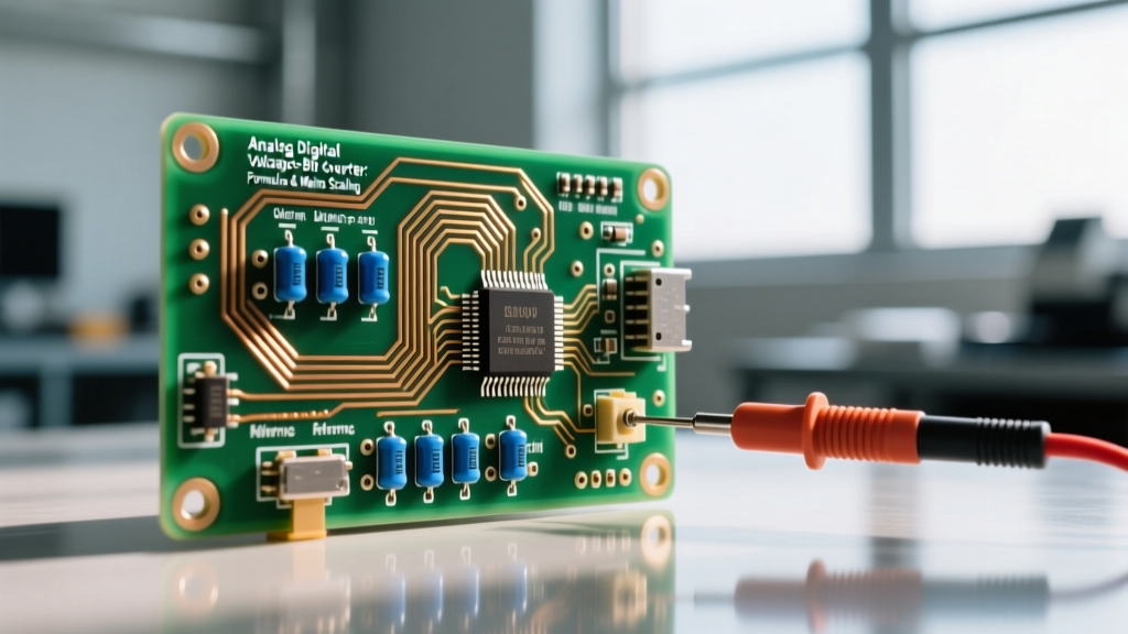
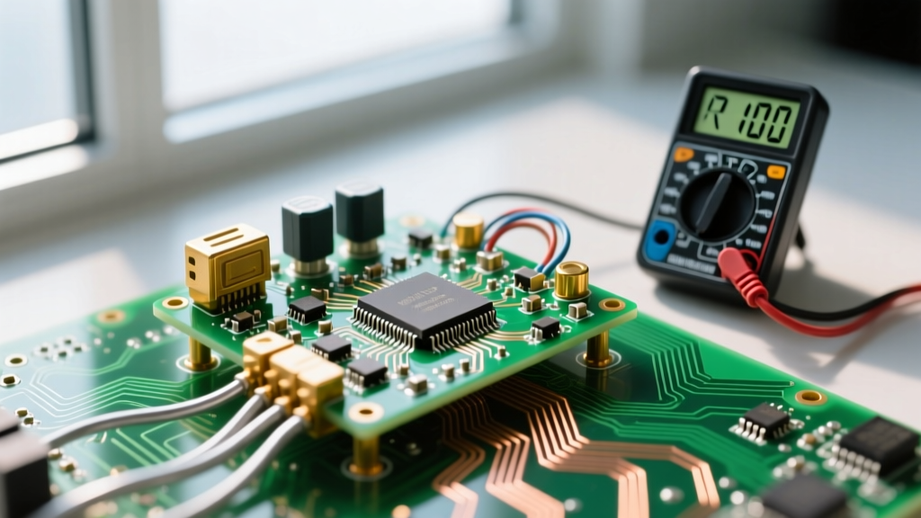
To check microfarads (µF) on a capacitor, you need a digital multimeter (DMM) with a dedicated capacitance setting or a specialized ESR/capacitance meter. The direct answer is simple: isolate the component, discharge it safely, and measure across the leads. However, a capacitor can show the correct microfarad reading while still being completely dead due to high internal resistance. Understanding how to read physical markings, identify visual failure modes, and select the right replacement is what separates a successful repair from a board that catches fire on the next power cycle.
Capacitors in switch-mode power supplies (SMPS), HVAC systems, and camera flashes can store lethal charges for days. Never short a capacitor with a screwdriver. Always discharge using a high-wattage resistor (e.g., a 5W 100Ω ceramic resistor) attached to insulated probes, and verify the voltage is 0V with your DMM before touching the terminals.
Decoding Capacitor Markings and Codes
Before you can test a capacitor, you need to know its expected value. Manufacturers use different marking schemes depending on the physical size and chemistry of the component.
Electrolytic and Tantalum Capacitors
These are large enough to print the value directly. You will see something like 1000µF 25V. The microfarad value is explicit. The voltage rating is the maximum DC working voltage. For tantalums, a colored stripe indicates the positive anode; for aluminum electrolytics, a stripe with minus signs indicates the negative cathode.
Ceramic and Film Capacitors (The 3-Digit Code)
Small through-hole and surface-mount capacitors use a 3-digit EIA code. The first two digits are the significant figures, and the third digit is the multiplier (number of zeros), expressed in picofarads (pF).
- 104: 10 × 10⁴ pF = 100,000 pF = 100 nF = 0.1 µF
- 473: 47 × 10³ pF = 47,000 pF = 47 nF = 0.047 µF
- 221: 22 × 10¹ pF = 220 pF = 0.00022 µF
Following the numbers, you will often see a letter indicating tolerance: J (±5%), K (±10%), or M (±20%). For a deeper look into dielectric materials and coding, the SparkFun capacitor guide provides an excellent breakdown of ceramic classifications like X7R and C0G.
Capacitor Types and Selection Criteria
Knowing which type of capacitor to use for a specific job is critical. You cannot simply swap a ceramic for an electrolytic just because the microfarad rating matches. The table below outlines the selection criteria based on construction and electrical characteristics.
| Type | Dielectric / Construction | Typical Tolerance | Tempco / Stability | Best Use Case (Which Type for Which Job) |
|---|---|---|---|---|
| Aluminum Electrolytic | Aluminum foil + liquid/polymer electrolyte | ±20% (Standard) | Poor (Dries out over time, high ESR) | Bulk power filtering, audio coupling, low-frequency smoothing. |
| MLCC (Ceramic) | Multi-layer ceramic (X7R, C0G/NP0) | ±10% to ±20% | Excellent (C0G), Moderate (X7R) | High-frequency decoupling, RF circuits, timing oscillators. |
| Tantalum | Tantalum metal + manganese dioxide | ±10% to ±20% | Good (Stable capacitance over temp) | Space-constrained PCB filtering, medical/aerospace low-profile designs. |
| Film (Polypropylene) | Metallized plastic film | ±1% to ±5% | Excellent (Very low dielectric absorption) | AC line filtering, snubber circuits, high-power audio crossovers, motor run. |
Step-by-Step: How to Check Microfarads on a Capacitor
Think of a capacitor as a water tower and its Equivalent Series Resistance (ESR) as the friction in the pipe feeding it. A multimeter checking microfarads only measures the tower's volume. It ignores the pipe friction. Here is the proper bench procedure to measure the volume accurately.
1. Isolate the Component
Never trust an in-circuit capacitance reading. Other parallel components (resistors, semiconductors, other capacitors) will create parallel impedance paths, skewing your DMM reading wildly. Desolder and remove the capacitor entirely, or at minimum, lift one leg completely out of the PCB pad.
2. Zero Your Test Leads
Test leads have their own parasitic capacitance (usually between 0.1nF and 0.5nF). If you are measuring small ceramic capacitors, short the probes together and press the REL (Relative) or NULL button on your DMM (like the Fluke 87V) to subtract the lead capacitance from subsequent readings.
3. Measure and Compare
Set your DMM to the capacitance mode (the -| |- symbol). Connect the probes. For polarized electrolytics, red to positive, black to negative. Wait for the reading to stabilize—large value capacitors (e.g., 4700µF) can take several seconds to charge up to the DMM's test voltage and settle on a final number. Compare the result to the rated value plus the tolerance (usually ±20% for electrolytics). If a 1000µF cap reads 750µF, it has degraded and must be replaced.
4. The Missing Metric: Check the ESR
If you are repairing a switching power supply or a motherboard, measuring microfarads is not enough. A capacitor can read 1000µF perfectly but have an ESR of 15 ohms, rendering it useless at 100kHz switching frequencies. Use a dedicated ESR meter (like the Atlas ESR70 or a MESR-100) to check the internal resistance. For most SMPS applications, ESR should be well under 0.5Ω. Fluke's testing guidelines emphasize that high ESR is the primary cause of unexplained logic resets and power supply ripple.
Visual Failure Modes and Safe Substitution
Capacitors rarely fail without leaving physical evidence. Before you even hook up a meter, perform a visual inspection.
Visual Symptoms of Failure
- Doming / Bulging Vent: The top cross-scored vent on an aluminum electrolytic is pushed upward. This indicates internal gas generation from electrolyte boiling due to overvoltage or excessive ripple current.
- Leaked Electrolyte: A crusty brown or black residue around the base of the capacitor or on the PCB pads beneath it. This is highly corrosive and will eat through copper traces.
- Shattered or Cracked Ceramic: MLCCs fail mechanically. Flex-cracks from board bending or piezoelectric shock look like tiny hairline fractures near the solder joints.
- Exploded Casing: In extreme reverse-polarity or massive overvoltage events, the aluminum can will rupture, spraying paper and electrolyte across the enclosure.
How to Substitute Safely When the Exact Part is Missing
If you do not have the exact BOM part in your bins, follow these substitution rules to ensure safe operation:
- Voltage Rating: Must be equal to or greater than the original. Replacing a 16V cap with a 25V cap is perfectly safe (though physically larger). Never substitute a lower voltage rating.
- Capacitance (µF): For bulk power filtering, a ±20% variance is acceptable. For timing circuits (like a 555 timer oscillator) or resonant filters, the exact value is mandatory.
- Temperature Rating: Always substitute a 105°C rated capacitor for an 85°C rated one. Never put an 85°C cap in a circuit designed for 105°C, as it will dry out prematurely.
- ESR / Ripple Current: If the original was a "Low-ESR" series (e.g., Panasonic FR or Rubycon ZL), you must replace it with another Low-ESR part. Standard electrolytics will overheat and fail in high-ripple SMPS circuits.
For comprehensive derating and lifespan calculations based on temperature and ripple current, refer to the Cornell Dubilier Aluminum Electrolytic Application Guide, which remains the industry standard reference for power supply designers.
Frequently Asked Questions
Can I check microfarads on a capacitor without removing it from the board?
Generally, no. Standard multimeters inject a low-frequency AC test signal that will be shunted by parallel semiconductors and other passive components, giving you a falsely high or completely erratic reading. While specialized in-circuit ESR meters can sometimes identify dead capacitors without desoldering by using high-frequency pulses, they do not accurately measure the actual microfarad capacitance value in-circuit. For a true µF measurement, isolate the part.
Why does my multimeter show the correct microfarads but the circuit still fails?
This is the classic "ghost capacitor" problem. The dielectric layer inside the capacitor has degraded, or the electrolyte has partially dried out. This increases the Equivalent Series Resistance (ESR) and Equivalent Series Inductance (ESL). Your DMM's capacitance test operates at a very low frequency (often 100Hz or less) and only measures the static charge storage. At the 100kHz+ operating frequency of a modern switch-mode power supply, the high ESR causes the capacitor to act like a resistor, generating heat and failing to filter high-frequency noise. You must test with an ESR meter to catch this.
How do I test a start/run capacitor on an HVAC compressor?
HVAC motor run capacitors are typically rated in the 5µF to 80µF range at 370V or 440V AC. Because they operate on AC mains, they can hold dangerous charges. Discharge the terminals with a 20kΩ 5W resistor. Use a dedicated HVAC multimeter (like the Fieldpiece SC77) or a DMM with a high-voltage capacitance range. The industry standard tolerance for motor run capacitors is +6% / -10%. If a 40µF capacitor reads below 36µF, the compressor will struggle to start, draw locked-rotor amperage, and trip the thermal overload. Replace it immediately.
What does the "MFD" marking mean on older motor capacitors?
MFD stands for "microfarad." It is an archaic abbreviation that was commonly used on older motor run capacitors and vintage electronics. It means exactly the same thing as µF or uF. If you see a capacitor marked "40 MFD 370 VAC," you need a 40µF, 370V AC replacement. Do not confuse MFD with millifarads (mF); in the context of legacy motor capacitors, MFD always means microfarads.