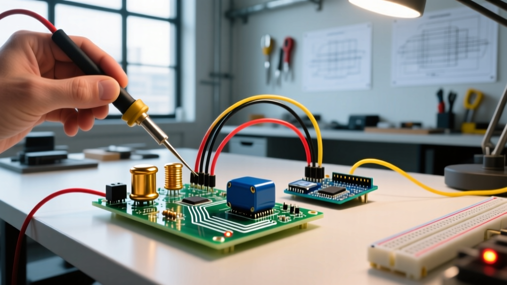

A high pass RL filter is a series resistor-inductor circuit where the output voltage is measured across the inductor, allowing high-frequency signals to pass while attenuating low-frequency signals. In a real circuit, this configuration changes your signal's frequency spectrum by blocking DC and low-frequency AC (attenuating them at -20dB per decade) while simultaneously introducing a phase lead that shifts the signal timing. Builders most commonly confuse the RL high pass filter with the RC high pass filter (which uses a capacitor and dominates audio applications) or the RL low pass filter (where the output is incorrectly taken across the resistor instead of the inductor).
The Working Principle and Cutoff Frequency
To understand how this filter works, you have to look at the inductor's reactance. An inductor's opposition to alternating current, known as inductive reactance ($X_L$), is directly proportional to frequency. The formula is $X_L = 2\pi fL$. At DC (0 Hz), the inductor is essentially a dead short (ignoring the tiny DC resistance of the wire coil). As frequency increases, the inductor's impedance rises, dropping more voltage across itself and leaving less across the series resistor.
Because we wire the resistor and inductor in series and take our output across the inductor, low frequencies see a low $X_L$ and get shunted to ground through the inductor's near-zero impedance. High frequencies see a massive $X_L$, forcing the signal voltage to appear at the output terminals.
The critical dividing line between the "passed" and "blocked" frequencies is the cutoff frequency ($f_c$). This is the point where the resistance ($R$) exactly equals the inductive reactance ($X_L$), and the output voltage drops to 70.7% (-3dB) of the input voltage. The governing equation is:
$f_c = \frac{R}{2\pi L}$
Worked Numeric Example: Designing a 15.9 kHz RL Filter
Let's move off the whiteboard and onto the bench. Suppose you need to strip a 60 Hz mains hum and low-frequency sensor drift out of a high-speed digital pulse train, and you want a cutoff frequency around 15 kHz.
We will select a standard Vishay 1kΩ carbon film resistor and a Bourns 10mH radial inductor (part number 78FR10K-RC). Here is how the math plays out with real component values:
| Parameter | Symbol | Value | Notes |
|---|---|---|---|
| Resistance | $R$ | 1,000 Ω | Standard E12 value |
| Inductance | $L$ | 0.010 H (10 mH) | Bourns 78FR10K-RC |
| Cutoff Frequency | $f_c$ | 15,915 Hz | $1000 / (2 \times \pi \times 0.01)$ |
| Attenuation at 1.59 kHz | -20dB point | ~159 Hz | One decade below $f_c$ |
| Phase Shift at $f_c$ | $\theta$ | +45° | Output leads input |
Where You Meet RL High Pass Filters in Practice
If RC filters are so common, why bother with inductors? Inductors are bulkier, more expensive, and prone to picking up stray magnetic fields. However, RL high pass filters are strictly required in several specific electrical and electronic domains:
- RF Bias Tees: In radio frequency (RF) amplifier design, you often need to inject a DC bias voltage into an RF signal path without the DC entering the preceding AC-coupled stage. An inductor passes the DC bias (acting as a short) while the high-frequency RF signal passes through a series capacitor. While technically a combined network, the inductor's behavior here mirrors the low-frequency pass/high-frequency block inverse, but when configured as an RL high-pass at the input of a gate drive, it blocks low-frequency noise while passing fast switching edges.
- High-Current High-Frequency Filtering: Capacitors struggle with high RMS currents due to Equivalent Series Resistance (ESR) and dielectric heating. If you need to filter out low-frequency ripple on a 20A switching power supply rail while passing high-frequency transient data, a heavy-gauge air-core inductor in an RL configuration will handle the thermal load far better than an equivalently rated electrolytic or film capacitor.
- Peaking Coils (Edge Sharpening): In high-speed digital video and legacy CRT circuitry, an inductor is placed in series with a signal path (often with a damping resistor) to intentionally boost high frequencies. This compensates for the parasitic capacitance of long coaxial cables, sharpening the rising edges of digital pulses.
Common Confusions and Edge Cases
The biggest mistake hobbyists make on the bench is ignoring the Self-Resonant Frequency (SRF) of the inductor. Theoretical RL filter math assumes an ideal inductor. In reality, the physical coils of wire in a 10mH inductor have parasitic parallel capacitance.
For the Bourns 10mH inductor used in our example, the SRF is roughly 250 kHz. At 250 kHz, the inductor acts like a parallel LC tank circuit, and its impedance spikes to maximum. But above 250 kHz, the parasitic capacitance takes over, and the component effectively becomes a capacitor. This means your RL high pass filter will unexpectedly roll off and become a low pass filter in the VHF band. Always check the manufacturer's SRF spec sheet; for high-pass filtering into the MHz range, you must use much smaller inductance values (e.g., 10 µH or 100 nH) with correspondingly lower resistor values to maintain the same $f_c$ while pushing the SRF well above your operating band.
Another common confusion is the inductive kickback effect. If you pass a pulsed DC signal through an RL high pass filter, the inductor will resist the sudden drop in current when the pulse ends, generating a high-voltage negative spike (flyback). In sensitive digital logic, this spike can fry a microcontroller GPIO pin. You must often pair the RL filter with a clamping diode or a snubber network in physical installations.
Frequently Asked Questions
Why use an RL high pass filter instead of an RC filter?
You choose an RL configuration over an RC configuration when your circuit must handle high DC currents without saturation, or when you need to avoid the dielectric absorption and ESR heating issues inherent in large capacitors. RC filters are vastly superior for audio and low-power signal conditioning because resistors and capacitors are cheap, small, and non-magnetic. RL filters win in power electronics, RF biasing, and high-speed edge-sharpening where capacitor parasitics would ruin the signal.
Does a high pass RL filter block DC voltage completely?
In pure theory, yes. At 0 Hz (DC), the inductive reactance is zero, meaning the inductor acts as a short circuit to ground, and the output voltage is exactly 0V. In real-world bench practice, the inductor has a small DC Resistance (DCR)—usually a few ohms for a 10mH part. This creates a tiny, non-zero DC voltage divider with your series resistor. For a 1kΩ resistor and an inductor with a 2Ω DCR, about 0.2% of your DC input voltage will leak through to the output. For most signal applications, this is negligible, but in precision analog sensing, it must be accounted for.
What happens to the phase angle in an RL high pass circuit?
An RL high pass filter introduces a phase lead. At frequencies far below the cutoff, the output voltage leads the input voltage by nearly +90 degrees. Exactly at the cutoff frequency ($f_c$), the phase shift is exactly +45 degrees. As the frequency climbs well above the cutoff, the inductor's reactance dominates the circuit, the resistor's influence fades, and the phase angle approaches 0 degrees, meaning the high-frequency output is perfectly in phase with the input. This phase lead is the exact opposite of the phase lag seen in RL low pass and RC high pass filters.
For further reading on AC filter theory and inductor behavior, consult the Electronics Tutorials High Pass Filter guide and the All About Circuits AC Theory textbook. Always verify your specific component's SRF and DCR on the manufacturer datasheet before finalizing your PCB layout or breadboard prototype.


