The halfwave rectifier passes only one polarity of an AC waveform while blocking the other, making it the most fundamental AC-to-DC conversion topology. While largely obsolete for primary power rails in modern 2026 designs due to poor transformer utilization and high ripple, it remains highly relevant in ultra-low-cost trickle chargers, signal demodulation, simple relay drivers, and HVAC control circuits where a few extra dollars for a bridge rectifier or switching IC cannot be justified.
If you are designing a power supply today, you need to know exactly what you are sacrificing by choosing a single diode over a bridge or a switcher. Below is the direct engineering data on efficiency, thermal limits, and the exact math required to keep a halfwave supply from destroying your transformer or browning out your microcontroller.
Topology Comparison: Halfwave vs. Full-Wave vs. Switching
Before committing to a single diode, evaluate the load. If your load requires tight voltage regulation or draws more than 100mA continuously, a halfwave rectifier will force you to use massive filter capacitors and heavily derate your transformer. Here is how the halfwave topology stacks up against standard alternatives for a typical 12VAC to 5VDC conversion.
| Topology | Theoretical Efficiency | Ripple Frequency | Diode / Switch Count | Transformer Utilization Factor (TUF) | Relative BOM Cost |
|---|---|---|---|---|---|
| Halfwave Rectifier | 40.6% | 1× Line (60Hz) | 1 Diode | 0.287 (Very Poor) | $0.05 |
| Full-Wave Bridge | 81.2% | 2× Line (120Hz) | 4 Diodes | 0.574 (Good) | $0.20 |
| Center-Tap Full-Wave | 81.2% | 2× Line (120Hz) | 2 Diodes | 0.574 (Good) | $0.40 (Requires special transformer) |
| Flyback (Switching) | 75% - 85% | 50kHz - 100kHz+ | 1 Switch, 1 Diode | N/A (Uses high-freq ferrite) | $1.50 - $3.00 |
Linear vs. Switching for Halfwave Loads: If your halfwave supply feeds a linear regulator (like an LM7805), the low ripple frequency (60Hz) means the input voltage sags deeply between peaks. A switching regulator (like a buck converter) can maintain regulation much closer to the trough of the ripple waveform, provided it has a low enough minimum input voltage. For loads under 50mA, linear is fine. For anything above 100mA, the heat dissipated by a linear regulator riding a 60Hz ripple wave makes a switching topology mandatory.
Design Example: 12VAC to 5VDC for an ESP32 Node
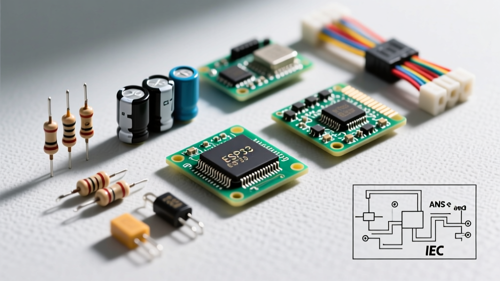
Let us design a halfwave power supply for an ESP32-WROOM-32 module powered by a standard 12VAC doorbell transformer. The ESP32 draws roughly 80mA on average but spikes to 250mA during Wi-Fi transmission bursts. We must ensure the voltage never drops below the regulator's dropout threshold during these 2-second TX bursts.
Input Specs and Peak Voltage Math
A "12VAC" transformer typically outputs closer to 14VAC under light loads, but we will design for the worst-case nominal 12VAC RMS.
- Vpeak = 12V × √2 = 16.97V
- Diode Drop (1N4007) ≈ 0.9V at surge currents
- Peak DC at Capacitor = 16.97V - 0.9V = 16.07V
Ripple Capacitor Sizing
Because a halfwave rectifier only charges the capacitor once per AC cycle, the discharge time is nearly the full period of the waveform (approx 16.6ms at 60Hz). The formula for peak-to-peak ripple voltage is:
Vripple = Iload / (f × C)
Where f is 60Hz for halfwave (compared to 120Hz for full-wave). If we allow a massive 6V peak-to-peak ripple to keep the capacitor size reasonable:
- C = 0.250A / (60Hz × 6V) = 0.000694 Farads
- Selected Capacitor: 1000µF, 25V rated (e.g., Panasonic EEU-FR1E102)
With a 6V ripple, the minimum voltage at the capacitor (Vmin) will be 16.07V - 6V = 10.07V.
Regulator Selection and Headroom Math
We need 5V out. Let us compare a standard linear regulator against an LDO and a switching buck.
- Standard Linear (LM7805): Requires ~2.0V dropout. Minimum input = 7.0V. Our Vmin of 10.07V is safe. However, average input is ~13V. Heat = (13V - 5V) × 0.08A = 0.64W. Requires a small heatsink.
- LDO (TI TPS7A47): Dropout is 310mV at 1A. Minimum input = 5.31V. Safe, but still dissipates 0.64W average.
- Switching Buck (TI LM2596): 85% efficiency. Heat = (5V × 0.08A) × (1/0.85 - 1) = 0.07W. No heatsink needed.
When power is first applied, a discharged 1000µF capacitor looks like a dead short. The initial surge current can exceed 20A, easily vaporizing the internal bond wires of a cheap 1N400x diode or tripping the doorbell transformer's internal thermal fuse. Always place a 10Ω to 22Ω, 2W wirewound surge resistor in series with the AC line before the diode to limit inrush to a safe ~1.5A.
Ripple, Noise, and Protection Requirements
The most defining characteristic of a halfwave rectifier is its noise profile. Unlike a full-wave bridge that pushes ripple up to 120Hz (making it easier to filter), the halfwave ripple sits squarely at the fundamental line frequency (50Hz or 60Hz). This low-frequency ripple is notoriously difficult to filter out with small ceramic capacitors and will easily couple into sensitive analog-to-digital converters (ADCs) or audio circuits.
Input Range and Protection Circuitry
If your AC source is a long run of thermostat wire or an industrial control transformer, you must protect against voltage spikes and reverse polarity conditions.
- Transformer Ringing (Flyback Spikes): When the diode snaps off at the zero-crossing, the transformer's leakage inductance can ring, generating reverse voltage spikes up to 3× the peak voltage. Place a bidirectional TVS diode (like the Littlefuse SMAJ18CA) directly across the transformer secondary to clamp these spikes.
- Reverse Battery Protection: If this supply is backing up a battery, a reverse-biased diode on the DC output is mandatory to prevent the battery from dumping current back through the linear regulator and the filter capacitor when AC power fails.
- Capacitor Bleeder: A 1000µF capacitor charged to 16V holds enough energy to deliver a painful shock or fry a shorted probe. Add a 10kΩ, 0.5W bleed resistor across the capacitor terminals to discharge it within 5 seconds of power removal.
Thermal Derating and Transformer Saturation Risks
The most frequently overlooked failure mode in halfwave power supplies is transformer DC saturation. Standard silicon-steel AC transformers are designed for symmetrical, zero-average AC current. A halfwave rectifier draws current in only one direction, introducing a net DC component to the secondary winding.
This DC current creates a static magnetic bias in the transformer core, shifting the operating point on the B-H curve closer to the saturation knee. When the AC peak aligns with this DC bias, the core saturates. Once saturated, the primary winding loses its inductive reactance and acts like a low-resistance wire across the mains. The transformer will draw massive, destructive magnetizing current from the wall, resulting in a loud 60Hz mechanical hum, extreme heat, and eventual thermal failure.
Derating Rules for Halfwave Supplies
To prevent core saturation and overheating, you must aggressively derate your transformer when using a halfwave topology. Refer to standard rectifier design guidelines for the following rules of thumb:
- VA Derating: A transformer feeding a halfwave rectifier must be rated for at least 2.5 to 3 times the actual DC wattage delivered to the load. If your load requires 10W of DC power, use a minimum 30VA transformer.
- Diode PIV Rating: The Peak Inverse Voltage (PIV) across the diode is not just the peak AC voltage. Due to the capacitor holding the peak voltage while the AC waveform swings to the negative peak, the diode must withstand 2 × Vpeak. For a 12VAC system (16.9V peak), the PIV is 33.8V. A 1N4001 (50V PIV) is technically sufficient, but standard engineering practice dictates a 1N4007 (1000V PIV) to handle transient mains surges for pennies more.
- Thermal Derating of the Diode: The ON Semi 1N400x series is rated for 1A average forward current. However, in a halfwave supply, the diode only conducts for a fraction of the cycle (often less than 20% of the time) to recharge the capacitor. This means the peak repetitive current during that short conduction angle can be 5A or more. Ensure your diode's IFSM (non-repetitive peak surge) and IFRM (repetitive peak) ratings exceed the calculated charging pulses, or parallel two diodes to share the thermal load.
By respecting the transformer utilization factor, sizing the filter capacitor for the 60Hz discharge curve, and derating the magnetic core for DC bias, a halfwave rectifier remains a highly reliable, ultra-low-cost solution for non-critical, low-power auxiliary loads.