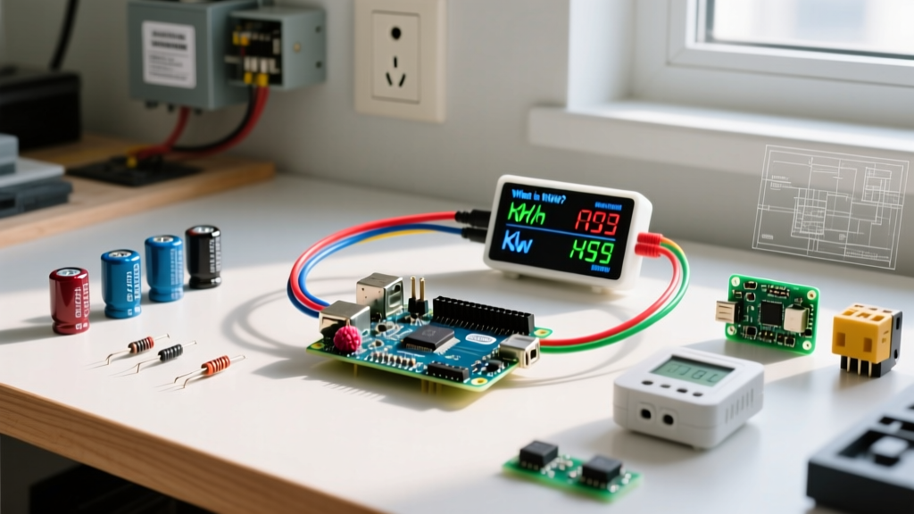
A GSM network is a standardized digital cellular telecommunications system that uses time-division multiple access (TDMA) to allow multiple devices to share the same frequency channel by dividing the signal into different time slots. If you are integrating a cellular telemetry module like a SIM800L, Quectel M95, or SIM900 into an ESP32 or Arduino project, understanding this definition is not just academic trivia. The TDMA time-slicing architecture directly dictates your power supply topology, your UART logic level shifting, and your PCB ground plane layout. When a GSM module transmits, it does not draw a steady current; it pulls massive, microsecond-scale transient spikes that will brownout your microcontroller if your decoupling network is undersized.
The Core Architecture and Frequency Bands
To design hardware that reliably registers on a GSM network, you must know which physical frequencies your module is transmitting on and how the channel spacing affects your RF front-end. The European Telecommunications Standards Institute (ETSI) defines these physical layer parameters. The network divides time into 4.615 ms frames, each containing 8 time slots. Your IoT device is typically assigned one slot to transmit its burst, meaning it is only actively drawing peak transmit current for roughly 12.5% of the time, but the instantaneous demand during that slot is extreme.
| Band Designation | Uplink Freq (Device to Tower) | Downlink Freq (Tower to Device) | Channel Spacing | Max Module Transmit Power |
|---|---|---|---|---|
| GSM-850 (CLR) | 824 – 849 MHz | 869 – 894 MHz | 200 kHz | 33 dBm (2.0 Watts) |
| GSM-900 (Primary) | 890 – 915 MHz | 935 – 960 MHz | 200 kHz | 33 dBm (2.0 Watts) |
| DCS-1800 | 1710 – 1785 MHz | 1805 – 1880 MHz | 200 kHz | 30 dBm (1.0 Watt) |
| PCS-1900 | 1850 – 1910 MHz | 1930 – 1990 MHz | 200 kHz | 30 dBm (1.0 Watt) |
Note: Lower frequency bands (850/900) penetrate building materials and foliage significantly better than 1800/1900 bands, which is why agricultural and remote solar IoT deployments prioritize quad-band modules that can fall back to 900 MHz.
What a GSM Network Changes in Your Circuit Design
Integrating a GSM module forces you to address three specific hardware domains: transient power delivery, logic level translation, and RF keep-out zones.
1. The 2-Amp Transmit Burst (Power Supply Sizing)
Because the GSM network uses TDMA, a Class 4 module transmitting on the 900 MHz band outputs 2 Watts of RF power. Accounting for the power amplifier's efficiency, the module will pull a peak current of 2.0 Amps from the VBAT pin. However, because it only transmits in one of the eight 577-microsecond time slots per frame, this 2A spike only lasts for 577 µs.
If your main power supply (like a standard 1A LiPo charge controller or a long, thin USB cable) cannot deliver 2A instantly, the voltage at the module's VBAT pin will sag. If it drops below the module's brownout threshold (typically 3.4V for a 4.0V nominal LiPo system), the baseband processor will hard-reset mid-transmission, creating an infinite boot-loop.
Let's calculate the local energy storage required to support the 2A burst without dropping more than 0.3V (keeping a 3.8V LiPo above the 3.5V safe operating limit).
Using the capacitor discharge formula: C = (I × Δt) / ΔV
- I (Peak Current) = 2.0 A
- Δt (Burst Duration) = 577 µs = 0.000577 seconds
- ΔV (Allowed Sag) = 0.3 V
Result: You need a minimum of 3,840 µF of low-ESR capacitance placed within 5mm of the module's VBAT pin. In practice, designers use a 4,700 µF or 10,000 µF low-ESR tantalum or supercapacitor, paired with a 100 nF ceramic capacitor in parallel to handle high-frequency switching noise.
2. UART Logic Level Shifting
Most legacy GSM modules operate their UART TX/RX pins at 2.8V or 1.8V logic levels. If you connect a 5V Arduino Uno directly to the RX pin of a SIM800L, the 5V logic high will exceed the absolute maximum ratings of the baseband chip, permanently destroying the silicon. You must use a bidirectional logic level shifter. A dual-MOSFET circuit using BSS138 transistors is the most reliable method, as it translates the 5V microcontroller signals down to the 2.8V module levels without the voltage drop and timing skew introduced by resistor-divider networks.
3. RF Ground Planes and Antenna Matching
GSM modules require a strict 50-ohm impedance path from the RF_OUT pin to the antenna. According to Analog Devices' guidelines on IoT antenna design, the ground plane beneath the RF trace must be continuous and unbroken by vias or digital signal lines. Furthermore, you must enforce a strict keep-out zone: no digital traces, no power planes, and no copper pours directly beneath the helical or PCB antenna. Digital noise from the ESP32's SPI bus coupling into the GSM antenna will desensitize the receiver, dropping your RSSI (Received Signal Strength Indicator) by 10 to 15 dBm.
Where You Meet This in Practice (and Common Confusions)
You will encounter GSM network integrations primarily in remote telemetry, off-grid solar monitoring, and agricultural soil-sensing nodes where WiFi is unavailable and LoRa gateways are out of range. Because GSM modules are incredibly cheap on the secondary market (often under $5 USD for a SIM800L breakout), they remain a staple in hobbyist and prototyping IoT builds.
What People Commonly Confuse GSM With
- GSM vs. CDMA: CDMA (used historically by Verizon/Sprint in the US) uses spread-spectrum code division rather than time slots. From a hardware perspective, a GSM module will physically not work on a CDMA network; the RF modems and baseband protocols are entirely different.
- GSM vs. LTE-M / NB-IoT: This is the most critical confusion in modern IoT. While GSM is a 2G technology, LTE-M and NB-IoT are 4G/LTE cellular standards designed specifically for low-power IoT. As telecom operators actively sunset 2G GSM networks to reclaim spectrum for 5G, the GSMA strongly recommends migrating new commercial IoT deployments to NB-IoT or LTE-M. NB-IoT modules (like the Quectel BC95) use different AT commands and require different network provisioning than legacy GSM.
- The Network vs. The SIM Card: Makers often assume that inserting an active nano-SIM into a module guarantees connection. However, many modern IoT SIMs (like those from Hologram or Twilio) require specific APN (Access Point Name) configurations sent via AT commands before the GSM module is allowed to attach to the packet-switched data network.
FAQ: Troubleshooting GSM Module Integrations
Why does my SIM800L keep resetting when I send an AT command to transmit?
This is almost always a VBAT voltage sag caused by the 2A TDMA burst. Measure the voltage directly at the module's VBAT and GND pins using an oscilloscope (a multimeter is too slow to catch a 577 µs drop). If you see the voltage dip below 3.4V during transmission, you need to add a larger low-ESR bulk capacitor (e.g., 10,000 µF) and ensure the power traces from your battery to the module are at least 40 mils wide to reduce parasitic resistance.
My module registers on the network (AT+CREG? returns 1), but I cannot open a TCP socket. Why?
Network registration (AT+CREG) only means the module has authenticated with the cell tower's control channel. Opening a TCP socket requires the PDP (Packet Data Protocol) context to be activated. Ensure you have correctly set the APN using the AT+CSTT command, brought up the wireless connection with AT+CIICR, and obtained an IP address via AT+CIFSR before attempting to open a TCP socket with AT+CIPSTART.
Can I use a standard 2G GSM module for a commercial product launching in 2026?
No. Most major carriers in North America, Australia, and parts of Europe have already shut down or are actively sunsetting their 2G GSM infrastructure. For a commercial product, you must design around an LTE-M or NB-IoT module (such as the Quectel BG96 or Sierra Wireless HL7800) to ensure long-term network viability and regulatory compliance.