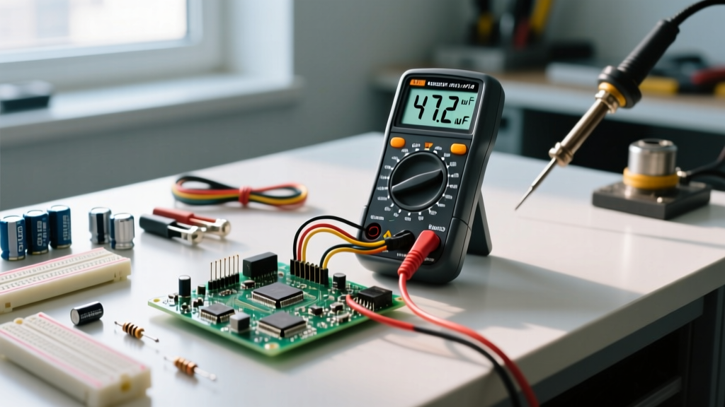
Greek symbols in science and electrical engineering are not just academic decoration; they are the standardized shorthand for physical reality. Whether you are calculating voltage drop, sizing a current shunt, or debugging an RF filter, the most critical symbols you must instantly recognize are Ω (Ohms/resistance), μ (micro prefix/permeability), ρ (resistivity), and ω (angular frequency). Misreading these on a schematic or faded PCB silkscreen can lead to a 1,000x calculation error, instantly destroying components.
The Master Greek Symbol Reference Table
Below is the definitive reference for the Greek alphabet as applied in electrical engineering, physics, and circuit design. This table assumes standard SI (International System of Units) conventions.
| Symbol | Name | Primary Electrical/Science Use | SI Unit / Value | Common Confusion |
|---|---|---|---|---|
| Ω / ω | Omega (Upper/Lower) | Resistance (Ω), Angular Frequency (ω) | Ohms (Ω), rad/s (ω) | Lowercase ω vs 'w' (watts) |
| μ | Mu | Micro prefix (10⁻⁶), Magnetic Permeability | μF, μH, μA; H/m | Visual confusion with 'm' (milli) |
| ρ | Rho | Electrical Resistivity, Volume Charge Density | Ω·m, C/m³ | Visual confusion with 'p' (power) |
| σ | Sigma | Electrical Conductivity, Surface Charge Density | S/m (Siemens per meter) | Confused with summation in math |
| ε | Epsilon | Permittivity of a dielectric material | F/m (Farads per meter) | Confused with 'e' (Euler's number) |
| λ | Lambda | Wavelength | Meters (m) | Rarely confused, but critical in RF |
| φ / ϕ | Phi | Phase Angle, Magnetic Flux | Radians (rad), Webers (Wb) | Phase angle vs θ (theta) usage |
| θ | Theta | Thermal Resistance, Phase Angle (alternate) | °C/W, Radians (rad) | Thermal vs electrical phase angle |
| Δ | Delta (Upper) | Change in a variable, Delta (3-phase) config | Dimensionless (change) | Delta config vs Wye (Y) config |
| η | Eta | Efficiency | Percentage (%) or ratio | Confused with 'n' (turns ratio) |
Standard Variants: IEEE vs. IEC vs. Legacy UK
While the NEC (US) and IEC (International) dictate wire colors and physical installations, their parent engineering bodies dictate how Greek symbols in science are applied to schematics. According to NIST Special Publication 811 and international drafting standards, regional variations still cause friction in global design teams.
| Feature | IEEE 315 (US Standard) | IEC 60617 (International) | Legacy UK (BS 3939) |
|---|---|---|---|
| Phase Angle | Typically uses θ (theta) for impedance phase angle. | Typically uses φ (phi) for phase difference (e.g., power factor cos φ). | Historically mixed; older texts use φ for flux and θ for phase. |
| Micro Prefix | Strictly μ. In plain text CAD, 'u' is accepted (e.g., uF). | Strictly μ. IEC 60027 forbids 'u' in formal documentation. | Older schematics sometimes used 'mfd' instead of μF for capacitors. |
| Angular Freq. | Uses ω (omega) = 2πf. | Uses ω, but heavily favors stating 'f' (Hz) on block diagrams. | Same as IEEE. |
| Thermal Res. | Often uses RθJA (Theta junction-to-ambient). | Often uses Rth (subscript 'th' instead of Greek theta). | Uses Rth. |
Rows People Get Wrong (And How to Fix Them)
Misinterpreting Greek symbols in science and electronics usually happens when handwritten notes, low-resolution PDFs, or worn silkscreens blur the lines between Greek and Latin characters. Here are the most dangerous mix-ups:
- μ (mu) vs. m (milli): This is the most costly error in electronics. μ means 10⁻⁶ (micro). m means 10⁻³ (milli). If a schematic calls for a 100μH inductor and you install a 100mH inductor, your switching regulator will likely saturate the core and destroy the MOSFET. Fix: Always verify the physical size. A 100mH inductor is physically massive compared to a 100μH inductor.
- ρ (rho) vs. p (power/pitch): In PCB trace calculations, ρ represents the bulk resistivity of copper (1.68 × 10⁻⁸ Ω·m). If you read this as 'p' and plug in power values into your trace width calculator, your copper traces will melt under load. Fix: Look for the units. ρ always has units of Ω·m. 'p' (power) is in Watts.
- ω (lowercase omega) vs. w (watts): Lowercase ω is angular frequency (radians/second). Uppercase W is Watts. If a formula reads P = ω × T (Power = angular frequency × Torque), and you substitute Watts for ω, the math collapses. Fix: Check the context. If the surrounding variables are time, frequency, or inductance, it is ω.
- η (eta) vs. n (turns ratio): η is efficiency (output/input). 'n' or 'N' is the transformer turns ratio (Np/Ns). Fix: Efficiency is always a decimal < 1.0 (or < 100%). Turns ratio can be any integer or fraction.
Decision Tree: Interpreting Faded or Ambiguous Markings
When you are reverse-engineering a board or reading a technician's faded lab notebook, you will encounter ambiguous characters. Use this decision path to safely interpret the marking and terminate in a concrete verification step.
| IF you see... | AND the context is... | THEN it is... | SAFE INTERPRETATION & ACTION |
|---|---|---|---|
| A symbol looking like 'u' or 'μ' | Next to a capacitor or inductor value | μ (Micro) | Assume μF or μH. Verify by checking component physical size against a known datasheet. |
| A symbol looking like 'p' or 'ρ' | In a formula with Length (L) and Area (A) | ρ (Rho / Resistivity) | Assume copper resistivity (1.68×10⁻⁸ Ω·m at 20°C). Do not substitute power. |
| A symbol looking like 'w' or 'ω' | Inside an AC impedance formula (Z = R + jX) | ω (Angular Frequency) | Calculate as 2 × π × f (where f is Hz). Do not substitute Watts. |
| A completely illegible Greek prefix on a current shunt | High-current measurement circuit | Ambiguous (μA vs mA) | DEFAULT PICK: Do not guess. Use a Keysight U1253B or equivalent 4.5-digit multimeter in 4-wire Ohms mode to empirically measure the shunt resistance, bypassing the faded marking entirely. |
Worked Example: Calculating Trace Resistance with Rho (ρ)
Let's apply ρ (rho) in a practical scenario. You are designing a PCB and need to know the voltage drop across a 10 cm long, 0.5 mm wide copper trace carrying 2A of current. The copper weight is 1 oz/ft² (which equates to a thickness of roughly 35 μm, or 35 × 10⁻⁶ m).
The Formula:
R = ρ × (L / A)
The Variables:
- ρ (Resistivity of Copper): 1.68 × 10⁻⁸ Ω·m (at 20°C ambient)
- L (Length): 10 cm = 0.1 m
- A (Cross-Sectional Area): Width × Thickness = (0.5 × 10⁻³ m) × (35 × 10⁻⁶ m) = 1.75 × 10⁻⁸ m²
The Calculation:
R = (1.68 × 10⁻⁸) × (0.1 / 1.75 × 10⁻⁸)
R = (1.68 × 10⁻⁸) × (5,714,285)
R ≈ 0.096 Ω (or 96 mΩ)
Voltage Drop (V = I × R):
V = 2A × 0.096 Ω = 0.192V (192 mV)
If you had misread ρ as 'p' (power) or failed to convert the μm thickness correctly, your calculated resistance would be off by orders of magnitude, leading you to undersize the trace and cause a thermal failure. For a deeper dive into standardizing these physical constants in your lab notebooks, refer to the NIST Guide to the SI.
By mastering these Greek symbols in science and engineering, you bridge the gap between theoretical physics and practical, reliable circuit design. Always verify ambiguous markings with physical measurement, respect the IEEE/IEC regional differences in phase notation, and never let a faded 'μ' compromise your power supply.