
The Direct Answer: Reading Codes and Measuring Capacitance
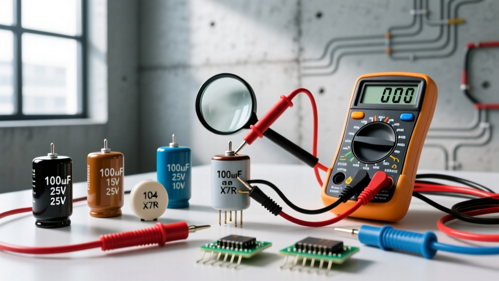
To find the capacitance of a capacitor, first check the physical markings: read the 3-digit EIA code on ceramics (e.g., '104' means 100,000 pF or 0.1 µF) or the direct microfarad (µF) print on electrolytics. If markings are missing, illegible, or you suspect degradation, safely discharge the component and measure it using a digital multimeter’s capacitance mode or a dedicated LCR meter. For precision analog circuits, always verify the temperature coefficient (tempco) and equivalent series resistance (ESR), not just the nominal capacitance.
Decoding Physical Markings: What the Numbers Actually Mean
Capacitor manufacturers use different labeling standards depending on the physical size and dielectric type of the component. Here is how to translate the ink on the casing into actual bench values.
The 3-Digit EIA Code (Ceramics and Films)
Small ceramic and film capacitors rarely have room for units. They use a 3-digit code where the first two digits are significant figures, and the third digit is the multiplier in picofarads (pF).
- Example: 104. The first two digits are '10'. The multiplier is '4' (meaning 10^4, or four zeros). Result: 100,000 pF.
- Conversion: 100,000 pF = 100 nF = 0.1 µF.
- Example: 222. '22' with two zeros = 2,200 pF = 2.2 nF.
You will often see a trailing letter indicating tolerance. J = ±5%, K = ±10%, and M = ±20%. A capacitor marked '104K' is a 0.1 µF part with a ±10% tolerance window.
Direct Print (Electrolytics and Large Tantalums)
Aluminum electrolytic and large polymer capacitors print the value directly: 470µF 25V. The voltage rating is just as critical as the capacitance here. Some older or specialized tantalum capacitors use color bands similar to resistors, but with the value in pF and a voltage band (e.g., a yellow band for 6.3V). When in doubt, cross-reference the physical case size (like EIA 3528 or 7343) with the manufacturer's datasheet.
Capacitor Type Comparison: Which Dielectric for Which Job?
Knowing the capacitance is only half the battle. The dielectric material dictates how the capacitor behaves under temperature changes, voltage bias, and high frequencies. Use this matrix to select the right type for your circuit.
| Type / Dielectric | Construction | Tolerance | Tempco / Stability | Typical Use | 2026 Avg Price |
|---|---|---|---|---|---|
| MLCC (C0G / NP0) | Class I Ceramic | ±1% to ±5% | Ultra-stable (0 ±30 ppm/°C) | RF filters, precision timing, PLL loops | $0.05 - $0.80 |
| MLCC (X7R / X5R) | Class II Ceramic | ±10% to ±20% | Poor (Loses up to 50% cap at rated DC bias) | Decoupling, bypass, general power rails | $0.01 - $0.20 |
| Aluminum Electrolytic | Foil and liquid/polymer electrolyte | ±20% | Moderate (Dries out over time/heat) | Bulk energy storage, low-freq smoothing | $0.10 - $2.50 |
| Tantalum (MnO2) | Pellet of tantalum powder | ±10% to ±20% | Good stability, high volumetric efficiency | Compact DC filtering, sample-and-hold | $0.20 - $1.50 |
| Polypropylene Film | Metalized plastic film | ±1% to ±5% | Excellent (Self-healing, low dielectric absorption) | Audio crossovers, snubber circuits, high-voltage | $0.50 - $5.00+ |
Visual and Electrical Failure Modes
Capacitors fail in specific, predictable ways based on their chemistry. Recognizing these symptoms saves hours of bench troubleshooting.
- Aluminum Electrolytic (The Bulge and Vent): Overheating or reverse voltage causes the internal electrolyte to boil, generating gas. Visual symptom: The scored cross on the top of the can bulges upward, or the rubber bung at the bottom pushes out, leaking a brown, fishy-smelling fluid. Electrical symptom: Massive spike in ESR, leading to power supply ripple.
- MLCC (The Invisible Crack): Board flexure during manufacturing or connector insertion cracks the brittle ceramic. Visual symptom: Often invisible without X-ray or dye-penetrant testing. Sometimes a faint hairline crack near the termination. Electrical symptom: Intermittent short circuit or piezoelectric 'squeal' when AC voltage is applied.
- Tantalum (Thermal Runaway): Standard MnO2 tantalums have very low tolerance for reverse voltage or high surge currents. Visual symptom: Catastrophic failure. The epoxy case splits, emitting thick white smoke and a bright flash. Electrical symptom: Dead short across the power rail.
How to Safely Substitute a Missing Capacitor
When the exact BOM part is out of stock, you must substitute safely. Use this decision tree to pick a replacement without compromising circuit stability or safety.
| If Replacing... | Then Choose... | Why & Constraints |
|---|---|---|
| C0G / NP0 Ceramic | Another C0G / NP0 | Mandatory for timing and RF. X7R will drift wildly with temperature and voltage, destroying filter cutoff frequencies. |
| X7R Ceramic | X5R, X7S, or C0G | X5R is fine if ambient temp stays below 85°C. C0G is an upgrade but physically larger. Never use Y5V (garbage tempco). |
| Aluminum Electrolytic | Same µF, Higher Voltage | Substituting a 25V part with a 50V part is perfectly safe and often improves lifespan. Never substitute with a lower voltage rating. |
| Tantalum | Polymer Aluminum or MLCC | Eliminates fire risk. If using MLCC, add a small series resistor (0.1Ω) to dampen LC resonance and prevent inrush ringing. |
| Film (Audio/Snubber) | Polypropylene or Polyester | Never substitute film with electrolytic in audio paths; the dielectric absorption and distortion will ruin the signal. |
The Bench Verification: Measuring with a Multimeter or LCR Meter
According to Fluke's measurement guidelines, a standard digital multimeter (DMM) is sufficient for basic verification, but an LCR meter is required for diagnosing ESR and dielectric losses.
Step-by-Step DMM Measurement
- Remove Power: De-energize the circuit. If measuring in-circuit, be aware that parallel semiconductor junctions and other capacitors will skew your reading. Out-of-circuit is always preferred.
- Discharge: Bridge the leads with a 1kΩ resistor for 5 seconds. Verify with the DMM in DC voltage mode that the part reads 0.00V.
- Select Capacitance Mode: Turn the DMM dial to the capacitance symbol (usually –|(– ).
- Zero the Probes: Touch the probes together and press the 'REL' (Relative) button to subtract the inherent capacitance of your test leads (usually 0.1nF to 0.5nF).
- Measure: Apply the probes to the capacitor. For polarized parts (electrolytic/tantalum), red to anode (+), black to cathode (-).
When to Upgrade to an LCR Meter
A DMM typically tests at a fixed, low frequency. However, capacitance is frequency-dependent. As noted in All About Circuits' component theory, large electrolytics should be tested at 120Hz (mains ripple frequency), while small ceramics must be tested at 1kHz or 10kHz to get an accurate reading. A dedicated LCR meter, like the Keysight U1733C or a budget DER EE DE-5000, allows you to select the test frequency and measure the Dissipation Factor (D) and ESR, telling you if an electrolytic is 'dried out' even if its nominal capacitance still reads correctly.
Default Bench Stock Recommendation
Stop guessing and buying random assortments. If you are stocking your lab for general-purpose repairs, microcontroller builds, and audio projects, buy these specific series:
- For Decoupling (0.1µF / 100nF): Buy X7R MLCCs in 0805 or 0603 packages. They are cheap, handle 50V easily, and cover 95% of digital logic bypassing needs.
- For Timing and Filters: Buy C0G/NP0 MLCCs. They cost slightly more but guarantee your 555 timers and active filters won't drift when the room warms up.
- For Bulk Power Storage: Buy the Rubycon ZL or Panasonic FR series aluminum electrolytics. They are low-ESR, 105°C rated, and will outlive standard 85°C generic caps by a factor of five in switching power supplies.